A lot of work has been done on multi-way constant beamwidth arrays, by the likes of David Smith (eXpanding Arrays) and Don Keele (Log Arrays).
I have worked to generalize these concepts in several ways.
While David Smith noted he had the greatest success using mixed order passive filters, I'm not sure that he ever derived the rules that relate crossover frequencies to filter order and Q for multi-way eXpanding arrays. Maybe he did and it was kept proprietary at Snell.
Keele worked with Horbach to generate digital crossovers that could be used on successive frequency bands for Log Arrays, since no more than 2 bands ever overlapped. This approach requires many amplifiers. Also, since the target response is linear phase, I strongly suspect that any non-linearities in the driver must be compensated for in the FIR filter design. That may significantly complicate the design process.
The approach I'm using generates a minimum phase target response for each driver, rather than a linear phase one. Also, the crossovers can be implemented passively, and each array driven from a single amplifier. No equalization is required to flatten the response on-axis. Additionally, the cabinets don't have to be curved.
Both the eXpanding arrays and the Log Arrays have used a "pair-wise" symmetry, with all the drivers in a line. Although you can find examples of deviation from this, I believe such deviations were made for sensitivity or power handling reasons; not to alter the directivity.
The pair-wise symmetry of those arrays can be considered a special case of fractal array, which allow for a basic configuration of drivers to be nested one inside the other. These drivers can number 2 or more, and be arranged specifically to obtain a desired polar response both vertically and horizontally (fractal arrays can be linear or planar, or possibly volumetric though I haven't looked into that). By using more than 2 drivers in each nest, greater directivity can be attained than with a pair, while still maintaining low sidelobe levels.
I highly suspect that Keele-Horbach filters would work with nests of greater variety than the symmetric pair of drivers, but I have not confirmed that.
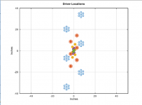
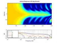
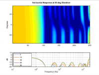
I am including 4 plots for a theoretical fractal array with 6 drivers in each nest. The nests have been configured to generate a much higher vertical directivity than horizontal directivity. The outer nests stay clear of each other, while the inner nests don't appear to (at least at this zoom level). Really, the inner most nest would be occupied by some type of planar (or possibly horn). EXpanding arrays and Log Arrays have the same issue.
The plots show:
1) Driver locations
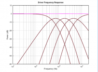
2) Frequency Response for drivers in each nest (with sum in purple)
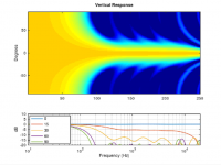
3) Vertical Polar Response
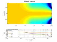
4) Horizontal Polar Response
I have incorporated concepts from this approach into a speaker system that I have built for myself, but I didn't follow it like a dogma. I made compromises and simplifications, yet I find the results to be very (very) satisfying.
At some point I may make a thread about my speakers, but for now I'd rather keep this theoretical. I only mention the compromises because I understand that the array pictured would be difficult to implement practically.
Questions and comments welcome.
I have worked to generalize these concepts in several ways.
While David Smith noted he had the greatest success using mixed order passive filters, I'm not sure that he ever derived the rules that relate crossover frequencies to filter order and Q for multi-way eXpanding arrays. Maybe he did and it was kept proprietary at Snell.
Keele worked with Horbach to generate digital crossovers that could be used on successive frequency bands for Log Arrays, since no more than 2 bands ever overlapped. This approach requires many amplifiers. Also, since the target response is linear phase, I strongly suspect that any non-linearities in the driver must be compensated for in the FIR filter design. That may significantly complicate the design process.
The approach I'm using generates a minimum phase target response for each driver, rather than a linear phase one. Also, the crossovers can be implemented passively, and each array driven from a single amplifier. No equalization is required to flatten the response on-axis. Additionally, the cabinets don't have to be curved.
Both the eXpanding arrays and the Log Arrays have used a "pair-wise" symmetry, with all the drivers in a line. Although you can find examples of deviation from this, I believe such deviations were made for sensitivity or power handling reasons; not to alter the directivity.
The pair-wise symmetry of those arrays can be considered a special case of fractal array, which allow for a basic configuration of drivers to be nested one inside the other. These drivers can number 2 or more, and be arranged specifically to obtain a desired polar response both vertically and horizontally (fractal arrays can be linear or planar, or possibly volumetric though I haven't looked into that). By using more than 2 drivers in each nest, greater directivity can be attained than with a pair, while still maintaining low sidelobe levels.
I highly suspect that Keele-Horbach filters would work with nests of greater variety than the symmetric pair of drivers, but I have not confirmed that.
I am including 4 plots for a theoretical fractal array with 6 drivers in each nest. The nests have been configured to generate a much higher vertical directivity than horizontal directivity. The outer nests stay clear of each other, while the inner nests don't appear to (at least at this zoom level). Really, the inner most nest would be occupied by some type of planar (or possibly horn). EXpanding arrays and Log Arrays have the same issue.
The plots show:
1) Driver locations
2) Frequency Response for drivers in each nest (with sum in purple)
3) Vertical Polar Response
4) Horizontal Polar Response
I have incorporated concepts from this approach into a speaker system that I have built for myself, but I didn't follow it like a dogma. I made compromises and simplifications, yet I find the results to be very (very) satisfying.
At some point I may make a thread about my speakers, but for now I'd rather keep this theoretical. I only mention the compromises because I understand that the array pictured would be difficult to implement practically.
Questions and comments welcome.
Attachments
Last edited:

Might sound daft, but would a smallish elliptical coaxial car speaker do the trick for the last couple of bands?
Just a thought.
Looks like a neat project, I must say, and I'd be very interested in details about the speakers you've built.
Chris
Just a thought.
Looks like a neat project, I must say, and I'd be very interested in details about the speakers you've built.
Chris
Thats an excellent directivity, both horizontally as well as vertically.
Pls share system pictures.
A few questions below
1)The polar plots show 50 to 250, how does it map to frequency?
2) The width of the speaker seems to be about 20 inches, is it correct?
It would help others build one, if you share more details. I for one want to build one.
Pls share system pictures.
A few questions below
1)The polar plots show 50 to 250, how does it map to frequency?
2) The width of the speaker seems to be about 20 inches, is it correct?
It would help others build one, if you share more details. I for one want to build one.
Last edited:
The horizontal beamwidth is 120 degrees down till ~700Hz. Thats quite good. Whats the reason for 120 since the 'norm' is 90 for home listening?
How are the polars along the diagonals?
What is a fractal array?
I am curious how you implemented such an array in your speaker. I have looked at Horbach-Keele arrays before and what keeps me from building one is that the high frequencies pose a challenge, as tweeters typically are too large to use these beamforming techniques on.
For experimenting low power class D amplifiers can be had for almost nothing. Add a 7.1 sound card and you have 8 fully DSP controlled channels.
Last edited:
Thats an excellent directivity, both horizontally as well as vertically.
Pls share system pictures.
A few questions below
1)The polar plots show 50 to 250, how does it map to frequency?
2) The width of the speaker seems to be about 20 inches, is it correct?
It would help others build one, if you share more details. I for one want to build one.
The X axis on the image plots shows the number of frequencies I used. The frequencies were log spaced, and octave (like a freeware matlab) doesn't allow me to easily put log axis labels in image plots. It does allow me to put a log axis on a line plot. The image plots and the line plots have the same frequency axis.
The width of the theoretical speaker depicted is about 20 inches. That includes a somewhat arbitrary decision about what radius to use for each driver.
Interesting concept, I can't wait to see your implementation of it (eventually I hope).
The driver locations do show each independent array part which actually makes this a true expanding array. 😉
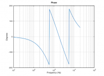
What does the combined phase response of this concept look like?
The driver locations do show each independent array part which actually makes this a true expanding array. 😉
What does the combined phase response of this concept look like?
How are the polars along the diagonals?
What is a fractal array?
I am curious how you implemented such an array in your speaker. I have looked at Horbach-Keele arrays before and what keeps me from building one is that the high frequencies pose a challenge, as tweeters typically are too large to use these beamforming techniques on.
For experimenting low power class D amplifiers can be had for almost nothing. Add a 7.1 sound card and you have 8 fully DSP controlled channels.
I see good insight in your questions. It's surprisingly easy to design a speaker with good vertical response at 0 degrees azimuth, and good azimuthal response at 0 degrees elevation, but bad response at other angles.
I have attached the diagonal plots you asked for. This particular theoretical array has good response everywhere. A version with only 4 drivers per nest that attempted to achieve similar vertical and horizontal response would have poor response on the diagonals.
My personal implementation (narrow vertical, wide horizontal response) uses an Aurum Cantus AST2560 in the center.
I am using the term fractal array to describe an array that is composed of nests of speakers that are similar, but differ in size. The first image in the OP shows 5 nests, depicted with different colors. The orange nest is a shrunken version of the blue nest, etc.
Attachments
Interesting concept, I can't wait to see your implementation of it (eventually I hope).
The driver locations do show each independent array part which actually makes this a true expanding array. 😉
What does the combined phase response of this concept look like?
I'll share my speaker project eventually, or someone else will.
It's not a phase linear result. Like any speaker, the phase could be linearized using DSP, though I haven't felt the need.
Attachments
Might sound daft, but would a smallish elliptical coaxial car speaker do the trick for the last couple of bands?
Just a thought.
Looks like a neat project, I must say, and I'd be very interested in details about the speakers you've built.
Chris
I hadn't really considered a coaxial. I see how it has some of the properties to facilitate the desired directivity. I worry that they are often too compromised, and if you're building something as complicated as this, you're likely looking for a no-compromise design. It's an interesting idea, though.
The horizontal beamwidth is 120 degrees down till ~700Hz. Thats quite good. Whats the reason for 120 since the 'norm' is 90 for home listening?
There was no particular reasoning behind the 120 degree beamwidth. I just wanted something to show some form of horizontal control, and have the smaller nests fit pretty well inside the bigger ones.
Personally, I think horizontal directivity ought to be controlled with room treatment: treat the early reflections, leave the late reflections alone.
I have played with similar idea, but used Edge and XDir for sanity check. My results told that longest vert/hor edge-to-edge distance for each "way" determined directivity. The effect of driver diameter per se vanished.
If this "fractal" concept works, it would be really nice...
Tekton is trying something like this TektonDesign LLC - Home
If this "fractal" concept works, it would be really nice...
Tekton is trying something like this TektonDesign LLC - Home
Speaker with this concept was introduced in Finland over 30 years ago as a diy kit. It was reference speaker of local Hifi magazine for a while. Multi-driver arrangement with 10 drivers was at 400-5000 Hz. Single woofer at ~40 cm from the floor.
One problem with this application was that woofer was omni which caused step to DI and power. Not so balanced result for casual off-axis listening.
Common problems are high price (without "cheap trick" drivers) and location of drivers which have to be very small to fit and work properly at upper mid...lower treble.
Coaxials, horns and wave guides offer better directivity control with lower price so this has not been popular design though very well known at least here.
We will need more details to replicate the design
I'm not entirely sure what you mean by "the design" in this context. I didn't start this thread to share a single design. I started it to share an example of a design concept that allows for CBT array design with horizontal control (or not) that doesn't require curved baffles, DSP, or equalization. And to gauge interest in that concept.
I'm not really sure what the best way to share this concept is, but since there appears to be interest it's probably time to figure that out.
I could write a paper, but that probably isn't sufficient for many people to incorporate the concept into a speaker design.
It might be better to get the concept integrated into a simulation program. I'm not aware of a program that allows the user to simulate a speaker like this: usually a 3-5 way speaker, with multiple drivers per nest (or "way"), arranged in particular geometry, with specific crossover topology that isn't really standard. If there is something, or if there's something close that could be easily modified, I'd be interested to talk to someone capable of making that modification.
Also, I'm not interested in helping design a commercial product without compensation. I'll help anyone design a speaker for personal use... just let me know the information and/or tools you require, and I'll see what I can do.
Last edited:
Hi bbutterfield,
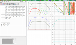
Thanks sharing, regarding simulation i tried dirty quick into VituixCAD a few days ago after member wesayso pointed me over here, it didn't get very good and reason is probably resolution of numbers i tried extract form your pictures into post 1 is not precise enough, result ended as attached below before i gave up, if you zoom into drivers area in below you can see the used X/Y numbers for driver position except for tweeter that was a bit impossible : ) by the way VituixCAD is free and work of member kimmosto so maybe you two in cooperation more or less can get this array to model as expected.
Thanks sharing, regarding simulation i tried dirty quick into VituixCAD a few days ago after member wesayso pointed me over here, it didn't get very good and reason is probably resolution of numbers i tried extract form your pictures into post 1 is not precise enough, result ended as attached below before i gave up, if you zoom into drivers area in below you can see the used X/Y numbers for driver position except for tweeter that was a bit impossible : ) by the way VituixCAD is free and work of member kimmosto so maybe you two in cooperation more or less can get this array to model as expected.
Attachments

Last edited:
Hi bbutterfield,
Thanks sharing, regarding simulation i tried dirty quick into VituixCAD a few days ago after member wesayso pointed me over here, it didn't get very good and reason is probably resolution of numbers i tried extract form your pictures into post 1 is not precise enough, result ended as attached below before i gave up, if you zoom into drivers area in below you can see the used X/Y numbers for driver position except for tweeter that was a bit impossible : ) by the way VituixCAD is free and work of member kimmosto so maybe you two in cooperation more or less can get this array to model as expected.
I'd generally be happy to work with the authors of simulators to incorporate this type of design concept. Kimmosto appears to be rather dismissive of the approach, so I'm not sure the interest is there. Perhaps a little convincing by pointing out that there are things you can do with this approach that are impossible to do with coaxials, horns, or waveguides would help. Horns and waveguids have problems generating drastically different beamwidths horizontally vs vertically, for example.
As for your attempt, I'll give some more details to get you closer:
The crossovers are cascaded 2nd order crossovers that result in a higher order. Like most 2nd order designs, there's a polarity inversion from one to the next. The cascading happens at each crossover frequency (500, 1180, 2785, and 6572 in the example in the OP). There are a couple of different Qs at play, depending on whether the particular crossover is bandpass or not, and the separation to the next crossover. In general the Qs vary from 0.5 to 0.57 or something like that. If you want to try to replicate the example I gave, I can get you all the details you would need. Alternatively, I could provide details on pretty much any theoretical variation of the idea. It might be good to start with a simpler one.
Hey that info on polarity helped alot thanks, in below graphs difference is simply inverted power amp for row two and four and now compare that to post 16 : )
For info your slopes was traced from post 1 so that each row of drivers is based on that traced slope and then their X/Y positions was sprayed around looking at those nice flowers : )
Can give it a new try if you support me some precise numbers for slopes and driver positions, VituixCAD can also visual show polars maps if we feed it some realistic predictions of off axis or use its build in tools to create off axis response relative to piston sizes.
Attachments
Last edited:
Kimmosto appears to be rather dismissive of the approach, so I'm not sure the interest is there.
My first simulator programmed late 80s' was specially designed to simulate this kind of multi-driver & multi-way concepts. That was limited and simplified application (compared to VituixCAD 2), though simulated also in-room response with up to 20 drivers in five ways.
Even though I've been interested in this concept quite a few years, simpler speakers and decent effort to room acoustics is less expensive and less complex path imo. That saves also work & money if opinion about good sound reproduction changes. Multiple ways with direct radiators is very good approach, but it does not have to be overshoot.
Anyway, VituixCAD 2 is fully capable for this without changes.
The problem with room acoustic treatments is that the important to treat surfaces are the difficult ones, that most people typically don't address. The floor and the ceiling are the most important, but we want to walk on the floor, and people hate to effectively lower their ceilings. The next most important is the front wall (behind the speakers) but that one often has a screen on it, so it is likely to get ignored. The sidewalls and backwall are the least important, and some people may prefer those actually go untreated, but they are often the only surfaces to get treated.
Regarding the simulation capability, it's one thing to be able to simulate something when the user knows every detail about what they want. It's another to bridge a potential gap in the user's knowledge by applying built in rules. For example, I can simulate a theoretical Fractal Array based on 3 parameters:
The woofer locations (which other nest locations are based on)
The woofer low pass frequency
The ratio between crossover frequencies (and a suitable default could be used for this).
It's that ability that I could bring to another simulation program, so users wouldn't be required to do the math themselves, and so that parameter changes could automatically update dependent aspects of the design.
Last edited:
- Status
- Not open for further replies.
- Home
- Loudspeakers
- Multi-Way
- Fractal Array Straight CBT with Passive XOs and no EQ