If you make angle measurements of drivers in cabinet and put data to Vituixcad, you can simulate crossover. No need to many extra components.
Are you saying that you'd just do a simulated xover and be good with it? Unfortunately that's not how it works. A simulated xover is useful to define a starting point. The development of the xover then needs measurements to show how things turn out in reality, listening tests to hear what it sounds like, and modifications to improve the outcome of these tests. This is an iterative procedure that takes a few cycles to find the best design.
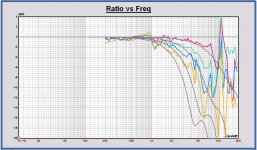
Just out of curiosity, I compared the off axis response of the ATC SM75 3 inch dome midrange (measurement by Troels) with the AE TD8M midrange (simulation model).
Not so much different, the ATC 3 inch is a little less directive.
More impact on directivity caused by the horn of the ATC, than I had expected.
In a way both midrange drivers can be combined with the same type of tweeter w.r.t. directivity.
We will see what the first measurements of the Volt midrange VM752 will tell us.
In the plot, the 10, 20, 30, and 40 degrees off axis responses of the ATC in color curves and the AE TD10M in grey.
All normalized to the on axis response.
Attachments
That's interesting, and it might allow similar tweeter implementations in the Monkey Coffin and the Tower XL. I have already asked the guys at Volt and they suggested that the straight "horn" of the VM752 may be even more directional than the ATC with the rounded "horn", but they did not provide any numbers. We'll see once I get the VM752 measured.
...the ATC has a convex horn ant the Volt a concave one. Understandable that the Volt will be a little more directional.
Actually, what is the reason for different directivity from a rounded or a straight "horn"? I don't quite see how to wrap my head around this.
If the guys at Volt suggest that their driver is more directional, I can understand it because sound waves are reflected more to the on axis than the off axis direction compared with the ATC rounded horn. In a way more power radiated on axis with the Volt.
Just like a curved front baffle radiates less power on axis than a flat one and has less baffle step boost.
Just some reasoning without any depth...
Just like a curved front baffle radiates less power on axis than a flat one and has less baffle step boost.
Just some reasoning without any depth...
Yes, this thread is alive!
The mailman was here with a box full of drivers in his hands. He wanted CHF 192.45 for import and stuff. It had to be cash, exact amount, no change possible! Go figure... Aaaaargh!! I hate how Swiss Post is stuck in the medieval times!!! This is supposed to be 2018!!!
The mailman was here with a box full of drivers in his hands. He wanted CHF 192.45 for import and stuff. It had to be cash, exact amount, no change possible! Go figure... Aaaaargh!! I hate how Swiss Post is stuck in the medieval times!!! This is supposed to be 2018!!!
") What a situation! The best drivers need some time to arrive.
What a situation! The best drivers need some time to arrive.Here's a draft idea for the baffle geometry to be used with the Monkey Coffin prototype. I used Pauls earlier drawing as an inspiration. I also added the horizontal offset for the mid and tweeter (roughly at golden ratio), which gave good results in Pauls simulations. While we have not yet decided on the tweeter, I have assumed a WG148 waveguide for now. The dashed pink circles indicate the internal structures of the mid and tweeter (VM752 magnet, WG148 flange).
Let me know what you think.
Let me know what you think.
Attachments
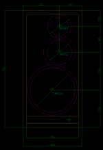
It looks good. Just one remark, the woofer is only at 4 mm distance of the port, that is very close. And if you want some margin on the woofer diameter, it is even closer. Also the drivers are very close to each other, about 7 - 8 mm, if no margin taken on the diameters.
Last edited:
Of course, it is only a remark out of an "aesthetics" point of view.Port should be as close to woofer as possibly can.
For the speaker look it is more nice to see some wood around the drivers also. I take about 1 cm minimum between the drivers and as the distance from the sides etc...
It is just my opinion.
I have few technical remarks.
I would align the driver centers on X axis. It's clear that offset is for mitigating the diffraction but you are getting different frequency responses offaxis left and right and differences can be substantial. Diffraction issue can be solved by faceted front baffle and it will look much better too.
I would align the driver centers on X axis. It's clear that offset is for mitigating the diffraction but you are getting different frequency responses offaxis left and right and differences can be substantial. Diffraction issue can be solved by faceted front baffle and it will look much better too.
Last edited:
I have few technical remarks.
I would align the driver centers on X axis. It's clear that offset is for mitigating the diffraction but you are getting different frequency responses offaxis left and right and differences can be substantial. Diffraction issue can be solved by faceted front baffle and it will look much better too.
We've had this discussion before. The asymmetry is no big deal (see Pauls simulations). Facettes don't do as much as people tend to believe (I confirmed this with measurements, see earlier posts about this) and can be difficult to make. This speaker is intended to be an easy-peasy project that can be done on a kitchen table.
I would agree that mitered or rounded edges don't do much unless they're quite substantial in size, which would not be a fit for this project. I can't speak for the unentered drivers although it's interesting that I see fewer commercial designs using them these days.
Curious, what depth would be needed for the box using those baffle dimensions?
Curious, what depth would be needed for the box using those baffle dimensions?
Curious, what depth would be needed for the box using those baffle dimensions?
The volume depends on the bass tuning. We have discussed this a lot, but no final decision yet.
We've had this discussion before. The asymmetry is no big deal (see Pauls simulations). Facettes don't do as much as people tend to believe (I confirmed this with measurements, see earlier posts about this) and can be difficult to make. This speaker is intended to be an easy-peasy project that can be done on a kitchen table.
I haven't seen any measurements in this thread of midrange and tweeter mounted on a baffle with and without facetes. When properly implemented they work great.
Simulation is one thing. Real world measurements of drivers in cabinets on and 90deg off axis will tell us true story.
If boxy shape of cabinet is prefered, for whatever reason that may be, i'd make front baffle covered with felt or foam to reduce diffraction effect and drivers without any offset on Y axis, but that's just me.
Last edited:
- Home
- Loudspeakers
- Multi-Way
- Open Source Monkey Box