Got a Behringer UMC1280 to do some multichannel DSP, so revisitng this project. I concur in earlier posts that the mids on the speakers seem to be reverse polarity. So double checked, not sure if I switched in wiring or not, but measurements confirm mine seemed to be reversed in MY setup (yours may be different). I used REW to measure the waveguides, and here are some of the results:
First shows the frequency responses. (Red) according to schematic, (Dark Green) mids reversed. There is a dip at 1.8khz vs with mid reversed, so I assume that confirms its 180 out of phase. Then progressive levels of stuffing, it drops the frequency repsonse on low end, so a peak filter at 1.2khz can take care of that.

This shows unwrapped phase. Something odd going on with red, vs. green which is smooth (mids reversed). So I think this is the way it should be and are leaving the mids reversed from what I had.

Here's the harmonic distortion. With the original, there is a spike, mids reversed (green) it goes down. You can see the effects of tuning with stuffing. Ideally, I would get this right, then tune each one individually using the DATS V3 and looking at the impedance graph. So despite the lower frequency drop, the overall distortion is at its lowest.

At this point, REW suggests a 1.2khz -4db filter.

So this is where I started orginally:

And this is where I ended (flipped mids and adding 1.2khz, -4db crossover):

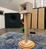
I think I did it right. Quick directivity plot around 0 - 45 degrees.

First shows the frequency responses. (Red) according to schematic, (Dark Green) mids reversed. There is a dip at 1.8khz vs with mid reversed, so I assume that confirms its 180 out of phase. Then progressive levels of stuffing, it drops the frequency repsonse on low end, so a peak filter at 1.2khz can take care of that.
This shows unwrapped phase. Something odd going on with red, vs. green which is smooth (mids reversed). So I think this is the way it should be and are leaving the mids reversed from what I had.
Here's the harmonic distortion. With the original, there is a spike, mids reversed (green) it goes down. You can see the effects of tuning with stuffing. Ideally, I would get this right, then tune each one individually using the DATS V3 and looking at the impedance graph. So despite the lower frequency drop, the overall distortion is at its lowest.
At this point, REW suggests a 1.2khz -4db filter.
So this is where I started orginally:
And this is where I ended (flipped mids and adding 1.2khz, -4db crossover):
I think I did it right. Quick directivity plot around 0 - 45 degrees.

First off: it's so cool seeing people build things I designed! I should do this more. I'm terrible at finishing things, but you guys aren't.
In regards to the distortion, keep in mind this waveguide was inspired by @bwaslo 's speakers that I bought, and it uses the same midranges. They're made by Gento and they're ridiculously inexpensive. It looks like the stuffing reduces the distortion from 5% to 0.2% , which isn't too shabby for a driver that costs about $1-$2.
I know that's insanely cheap, but there was a method to my madness:
1) the first one is that I've tried a LOT of small midranges, and dozens of the good ones are no longer available. For instance, bwaslo considered the Aurasound Whisper for his project, and I used them in my first Unity horn, 21 years ago. But the price of the Aurasound is all over the map, anywhere from $8 (back in the day) to $35 today: https://www.madisoundspeakerstore.c...7TovtbIIoaIu5hoJVVwn7cMhMMm4x_zr3heKjUsMuA1MM At $32 for four of them, they're compelling, at $140, you can do better. Possibly the best thing about the Gento isn't the price, it's that it's available all over the world.
2) It took me a few years to figure out some "cheats" to squeeze larger mids onto a Unity horn. At this point, I can reliably get 3"-4" midranges to work on a Unity horn. But it's tricky and I was hoping to put a design out there that was affordable and relatively easy to work with. For instance, I once made a Unity horn using a single 8" woofer and a compression driver. And it kinda worked. But it was definitely pushing the limits of what is possible; it had to use all kinds of byzantine tricks to make it (sorta) work.
I'm kind of prolific when it comes to "making waveguides", but the crazy thing is that 25% of my projects never get posted. Basically I'll make a waveguide in 2-4 hours, print it, measure it, then forget about it for one reason or another.
This is one of those; I don't think I've posted this. If I'm wrong, apologies for the double post.


This is one of those; I don't think I've posted this. If I'm wrong, apologies for the double post.
- Patrick Bateman
- Replies: 14
- Forum: Multi-Way
Have you tried plaster of Paris? It’s much thicker and would probably be better with no infill, but it won’t leak.The gyroid infill was awesome to allow the epoxy infill, unfortunately, the print leaked the epoxy through some voids.
Saw it being done by that YouTube channel with the British guy a few months after what I did with the laser speakers. Much cheaper to do that what I did. I presume a more watery mixture would be best. Epoxy allowed me to sand or drill and tap the speaker holes.
I have experimented with filling 5% gyroid infill prints with the plaster of paris method and filling them with fine sand. Plaster of paris is a mess i just didn't like and i feel like sand is moving a little bit under vibration. I thought about infusing the sand with some vegetable oil but i don't think its any less messy than plaster of paris 🙂
In the end i will mix sand, PVA and plaster of paris, as i found plaster to still have some ringing left.
In the end i will mix sand, PVA and plaster of paris, as i found plaster to still have some ringing left.
Does the epoxy get hot when it cures? If leaking is the issue then coating the print prior to filling would work. I would prefer epoxy over plaster, I just thought it would get too hot as it cures. I tried to fill with epanding foam once and it melted my horn so I stayed away from anything with heat.Saw it being done by that YouTube channel with the British guy a few months after what I did with the laser speakers. Much cheaper to do that what I did. I presume a more watery mixture would be best. Epoxy allowed me to sand or drill and tap the speaker holes.
Doesn’t get hot at all. Just get the crystal clear casting epoxy for slow cure. I would print it, then pour a gel coat over everything, get all the nooks and crannies. Fill it with water to test. Any final leaks, just put modelling clay or plumbers putty. Then fill it up. Once done, water base putty will wash away.
A for Ara posted a new speaker on their Instagram, it looks familiar to me lol
1st pic is the one from this thread, built by @Brinkman
Second is the new "A for Ara"
@cowanaudio any details on the new one?
1st pic is the one from this thread, built by @Brinkman
Second is the new "A for Ara"
@cowanaudio any details on the new one?
Attachments
Patrick,
About an hour south of me, I met with this person on FB marketplace when I bought some Dayton 12" PA310's from him. https://www.jwsound.live We started talking and he does a lot of work with MEH/Synergy style designs also Paraflex. I came by and listened to his system and heard the Solana prototype and it was just like the magic I remember from the Lambda Unity's when I lived near Nick McKinley. The 12" version of the MEH's were even better, it had that "This is about as good as it gets!" magic. Used a lot of FIR to optimize it too, not an expensive FIR, some cheap 10 channel ALIEXPRESS deal.
He's doing some wild stuff to design the horn, uses ATH4, take the results and designed a program to recursively optimize the design automatically to achieve certain parameters. Best part - he's giving away the designs for free! (With optional donation) with Plans and 3d models. If I wasn't invested into this project, I would have built his.
You should come by and listen to the latest version at some point! I think I had prototype A when you last visited. Lots of improvements since then and I think it surpasses the larger 2x12" in terms of SQ.
May have to be in a few weeks though. The two I have are out getting Klippel'd.
May have to be in a few weeks though. The two I have are out getting Klippel'd.
Last edited:
So I was "kinda" happy with the results, but disappointed the mids didn't go as low as I want it to. Its nice to see a consistent energy across the passband from the stuffing and figuring out the polarity of the mids. However, the fix is stuffing to take care of the 1.8khz resonance, at the expense of low end extension.
Had a conversation with Kravchenko_Audio over the weekend as we talked occasionally about audio related stuff. Was wondering if my rear chamber was modelled way too small and the effects of increasing it. He suggested modelling in HornResp and finding out what's going on there to duplicate the setup I have and from there, model what could be improved.
(Before I begin, this is not a complaint on the design - just wanted to share my experiences to help others when they encounter something like this in the future. Few midrange drivers work as well as the Gento, for the price. Its a bargain price and still available, so anything to help optimize this is a benefit for the community. Much appreciation to Mr Patrick Bateman for making this available for free! I could never have started building my own Synergy without this project.)
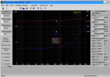
Below is DATSV3 data:
Gento driver (driver only), I use this measurement for HornResp driver data :

Test with Sealed back (no horn):

Modelled sealed enclosure only:
(Modelling this is close, HornResp shows about VRC 0.02L modelled give 689hz vs 695hz measured, so close enough for finding actual VRC)

Use REW to measure the frequency response and harmonics:
(In this case, the diaphragm excursion matches the simulation, notice the spike in harmonics corresponds to the peak excursion)

Now to measure sealed enclosure mounted to the horn (no stuffing). In PB's design, its a hole with a wide flare that entered the horn corner. In this case, the low end impedance peak lowers to 559hz and as a smaller peak now at 1.9khz, I presume this means more resoance contribution from the sealed chamber than the front:

REW measurement of a single driver in the horn (sealed back), no stuffing:
(Notice same peaks as what was measured with DATS - peaks have increase in distortion)

OK - time to model this in HornResp:

OK - so this is promising! You can see that the peaks match what I have measured. The magnitude is different.
Now, let's simulate it with some stuffing on the front:

So this shows why stuffing works in the port, it reduces that 1.9khz excursion, at the expense of low frequency extension.


OK - so what's next? I believe I need to solve the impedance peaks. We know stuffing the ports works, but at the expense of low end extension.
I could:
A. Modify the entrance ports, but I don't want to redesign a new horn.....yet.
B. Modify the rear chamber. Making the rear chamber larger, from 0.2Lto 0.1L, lowers the resonance frequency, but increases the peak excursion:


However, the horn will be operated between the peaks, but will need a step filter for the highs. I am going to investigate taming the peaks with a metamaterial rear chamber. That is why I wanted to investigate enlarging the rear enclosure, to see if I could actually add this in the design, which I could definitely fit an extra .7L work of metamaterial to accomplish that. Anyway, that's it for now!
Had a conversation with Kravchenko_Audio over the weekend as we talked occasionally about audio related stuff. Was wondering if my rear chamber was modelled way too small and the effects of increasing it. He suggested modelling in HornResp and finding out what's going on there to duplicate the setup I have and from there, model what could be improved.
(Before I begin, this is not a complaint on the design - just wanted to share my experiences to help others when they encounter something like this in the future. Few midrange drivers work as well as the Gento, for the price. Its a bargain price and still available, so anything to help optimize this is a benefit for the community. Much appreciation to Mr Patrick Bateman for making this available for free! I could never have started building my own Synergy without this project.)
Below is DATSV3 data:
Gento driver (driver only), I use this measurement for HornResp driver data :
Test with Sealed back (no horn):
Modelled sealed enclosure only:
(Modelling this is close, HornResp shows about VRC 0.02L modelled give 689hz vs 695hz measured, so close enough for finding actual VRC)
Use REW to measure the frequency response and harmonics:
(In this case, the diaphragm excursion matches the simulation, notice the spike in harmonics corresponds to the peak excursion)
Now to measure sealed enclosure mounted to the horn (no stuffing). In PB's design, its a hole with a wide flare that entered the horn corner. In this case, the low end impedance peak lowers to 559hz and as a smaller peak now at 1.9khz, I presume this means more resoance contribution from the sealed chamber than the front:
REW measurement of a single driver in the horn (sealed back), no stuffing:
(Notice same peaks as what was measured with DATS - peaks have increase in distortion)
OK - time to model this in HornResp:
OK - so this is promising! You can see that the peaks match what I have measured. The magnitude is different.
Now, let's simulate it with some stuffing on the front:
So this shows why stuffing works in the port, it reduces that 1.9khz excursion, at the expense of low frequency extension.
OK - so what's next? I believe I need to solve the impedance peaks. We know stuffing the ports works, but at the expense of low end extension.
I could:
A. Modify the entrance ports, but I don't want to redesign a new horn.....yet.
B. Modify the rear chamber. Making the rear chamber larger, from 0.2Lto 0.1L, lowers the resonance frequency, but increases the peak excursion:
However, the horn will be operated between the peaks, but will need a step filter for the highs. I am going to investigate taming the peaks with a metamaterial rear chamber. That is why I wanted to investigate enlarging the rear enclosure, to see if I could actually add this in the design, which I could definitely fit an extra .7L work of metamaterial to accomplish that. Anyway, that's it for now!
Attachments

The Solana surpasses the JMOD MEH?You should come by and listen to the latest version at some point! I think I had prototype A when you last visited. Lots of improvements since then and I think it surpasses the larger 2x12" in terms of SQ.
Against V1, I think so. Subjectively, it has a more accurate/consistent timbre. It's also more enjoyable to listen to for longer sessions and is less fatiguing. It misses out on the explosive dynamic ability the JMODs have though.The Solana surpasses the JMOD MEH?
Objectively speaking, the JMODs have some directivity inconsistencies, with lobing occuring 1.3kHz and 7kHz on the vertical especially. I would imagine that would translate largely to why I think the solanas sound better. These issues have been mostly resolved in the v2 design though.
I had a sighted session to A/B the JMOD 2.0s in the far field against Solanas in the near field a few days ago, and I do think the 2.0s have gotten the edge (not to mention way more headroom).
Thank you for the in depth reply John, that was exactly the information I was after. 🙂
I have been toying with the idea of making a JMOD MEH horn.
I have been toying with the idea of making a JMOD MEH horn.
- Home
- Loudspeakers
- Multi-Way
- "Unitized" Image Control Waveguide