People have tried that multiple small hole thing with mixed results.
Certainly, moving the holes further out would work better and shouldn't be that hard to do. Once you've backed the holes with something, you can fill them right up with bondo. You really want the holes as far from the apex as you can get and still have enough bandwidth for the XO.
I'd also suggest applying a 4 or 5 cycle frequency dependent window, FDW, to your REW frequency response. It will give you a clearer view of the direct wave and is a good guide for EQ. And if you are EQing to a typical house curve that falls through the treble, it wouldn't be totally out of the question to fill in that dip at 6 khz.
Lots of these synergies have been done w/o need for staggered holes. That might broaden the null but does that really help? OTOH if you "move" holes one at a time you will see the effect of staggered holes.
The best thing to do is to place them as far from the apex as you can make work and no larger than necessary to support your target max SPL. If you do that well then you can hope that elongated holes will hide in the horn corners for minimum impact on your polars. If your goal is an in-home SPL level then smaller holes will suffice. If you want to be able to hit 130 db+ then your holes will be on the large side.
You also need to respect the rule that the circumference of the horn at the mid entry point be <= one wavelength at the upper XO frequency - so don't move them too far out.
But the null out at 6 Khz might be a result of discontinuities at the throat and be fixed by using modeling clay to smooth the round to rectangular transition. That would be the low hanging fruit and moving the holes an optimization.
The thing is, I'm planing to cross over at 1kHz and the 1/4wl of that is 8.6cm. When the internal acoustic path of the CD (6,5cm) is accounted for, it doesn't leave much space...
I'm not sure if I should be counting the 1/4wl from the acoustic source of the CD instead of just taking it from the horn throat..
😕
I'm not sure if I should be counting the 1/4wl from the acoustic source of the CD instead of just taking it from the horn throat..
😕
you definitely need to include the CD's internal path length. I used the same BMS4550 and got good correlation with sims using 5.5 cm for its acoustic path length. Acoustic center is usually a short distance in front of the actual diaphragm.
Don't forget these distances are on the axis of the horn. With a 90H horn you get 1.414x the distance along the horizontal horn wall.
But you are correct that it is tight. I recall having an on axis distance from the apex of 2.25" = 5.7 cm and I see L12=8.9 cm in an HR model commented "L12 adjusted to match proto response" but that is inconsistent with the 5.5 cm figure I quoted in my first paragraph. but if I change the sim to L12=11.2 cm, I still make a 1 Khz XO.
So I'm confused also. HR seems to be putting the cancellation null at a higher frequency than you get from the 1/4 wavelength calculation and, given my results, HR is correct. I never noticed this before; just trusted the sim.
I too find it's best to retain a sense of humor when embarking on new adventures...
As far as the Hornresp thing, perhaps the Hornresp author might chime in with some description of how he modeled the compression driver internal path length (if any) and whether or not his model consistently predicts power loss effects out of a multiple entry horn at frequencies at other than 1/4 wavelength based on an area fraction of the "downstream" port areas.
Chris
Last edited:
The thing is, I'm planing to cross over at 1kHz and the 1/4wl of that is 8.6cm. When the internal acoustic path of the CD (6,5cm) is accounted for, it doesn't leave much space...
I'm not sure if I should be counting the 1/4wl from the acoustic source of the CD instead of just taking it from the horn throat..
😕
Just copy where Danley puts the taps.
Trust me, it works 🙂
The only real improvement I've been able to do to the taps is by making them a phase plug instead of a hole. But you need a 3D printer for that.
the HR author only wrote the simulator; he didn't model the horn but maybe he can shed some light on this anyway.
When I modeled my Synergy, I got the horn Sx params from BWaslo's spreadsheet, then added the thickness of my CD mounting plate and the assumed internal path length of the CD to the L12 from the spreadsheet; entered the driver parameters, initial guesses for port area and length and clicked calculate. To my mind adding these values to the L12 extends the horn backwards, pushing the reflection point backwards.
One question is where in the CD does the sound reflect from: the diaphragm or the phase plug or the acoustic center, some distance in front of one or the other. I was attempting to answer this question pragmatically when I changed the L12 value in the simulator to one that gave best agreement with measurements - in particular the frequency of the reflection null. this was done long ago and apparently my notes and recollection leave something to be desired.
In the simulation I referenced, I have an 8.9 cm L12 and a null at 1495 Hz.
The wavelength of 1495 Hz is 9" or 22.98 cm. 1/4 lambda = 5.74 cm
Based on an L12 of 8.9 cm, we would expect a null at 965 Hz
Why that difference?
One possible reason is that the simulation doesn't match the horn, despite it having been CNCed to the dimensions in the spreadsheet. It certainly doesn't in some respects. I built a 90x45 rectangular horn. HR converts that into an equivalent axisymmetric horn with an angle of 36 degrees. That different geometry just might be the explanation we are looking for.
Thought experiment -- if you fed a tweeter output through a long narrow pin hole tube (not that there's any reason to) and then measured the reflection nulls in the midrange response, would the null correspond to the tweeter diaphragm way back at the end of the tube or to the throat/wall where the pinhole starts? Pretty sure it would be the latter, because very little of the pressure wave from the midrange would go back through the pin hole -- you can't be thinking in absolutes when dealing with physical geometry. And if so, then the position for a null off a normal compression tweeter will probably be some small distance forward of the diaphragm since the effective path cross sectional area gets pretty small as it approaches the tweeter diaphragm. Hornresponse doesn't know about the internal geometry of the compression driver, so you can't expect it to show the effects of it. So, expect to use some empirical measurement when doing this stuff, unless you can do a very detailed finite element model of all the parts.
That is a good example but one closer to home is the typical compression driver phase plug that has a set of axial or circumferential slits in it through which the sound passes. For CDs with phase plugs like that, I think the phase plug would be the reflection point.
The BMS4550 isn't like most CDs however. Patrick Bateman has dissected one in the past. Perhaps he can comment based upon what he has seen inside. I think maybe the sound traverses first the outside and then back inside an internal tapered tube. If so, then it might be the reflection point is midway on that path.
The BMS4550 isn't like most CDs however. Patrick Bateman has dissected one in the past. Perhaps he can comment based upon what he has seen inside. I think maybe the sound traverses first the outside and then back inside an internal tapered tube. If so, then it might be the reflection point is midway on that path.
...Hornresponse doesn't know about the internal geometry of the compression driver, so you can't expect it to show the effects of it. So, expect to use some empirical measurement when doing this stuff...
That's my understanding of the tool, too. In my experience, the actual measured power loss due to the next set of off-axis ports (on the real device--not simulated results) starts at the top lip of the port, is maximal at the widest part of the port, and finally loses its effects at the bottom lip of the port--farthest away from the on-axis throat--all corresponding to 1/4 wavelength from the throat entrance of the horn, i.e., not the compression driver acoustic center.
However, my experience is with 2" compression drivers and woofers, not midrange ports, and is in the 400-500 Hz range where this effect occurs.
I've found that the off-axis port related SPL loss is a pretty strong function of the off-axis angle from the horn's centerline. After EQing the loudspeaker to flat response, the SPL loss is correlated at the horn's design coverage half angle from the centerline in that horn axis with the off-axis ports (i.e., at the off-axis angle corresponding to the straight-sided wall angle). The relative SPL loss is much less pronounced at smaller off-axis angles.
Chris
The BMS4550 isn't like most CDs however. Patrick Bateman has dissected one in the past. Perhaps he can comment based upon what he has seen inside. I think maybe the sound traverses first the outside and then back inside an internal tapered tube. If so, then it might be the reflection point is midway on that path.
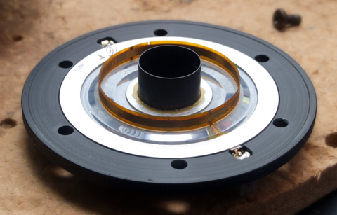
Paul Spencer took one apart and described it in his blog looks like the picture above
Red Spade Audio: BMS 4550 compression driver
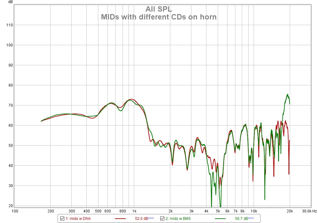
After an hour of looking for it I found measurements of an early proto showing mids with different CDs on the horn. I'm not sure what it proves but I thought I would show the picture and let you judge for yourselves.
Strangely, the response for the DNA360 which ostensibly has a shorter internal path comes down a little quicker than for the BMS4550. I expected a different result but I think the reflection null is masked somehow and we are just seeing the acoustic lowpass filter of the bandpass alignment.
Strangely, the response for the DNA360 which ostensibly has a shorter internal path comes down a little quicker than for the BMS4550. I expected a different result but I think the reflection null is masked somehow and we are just seeing the acoustic lowpass filter of the bandpass alignment.
Attachments
perhaps the Hornresp author might chime in with some description of how he modeled the compression driver internal path length
The acoustic path from the diaphragm to the outlet of a compression driver is normally modelled using a throat chamber and a throat adaptor.
and whether or not his model consistently predicts power loss effects out of a multiple entry horn at frequencies at other than 1/4 wavelength based on an area fraction of the "downstream" port areas.
1/4 wavelength has no significance to the generalised simulation model used in Hornresp.
Thanks David. Could you briefly describe the relationship or solver used (...without revealing any secrets...).
Chris
Chris
soo, I did some more measurements..
I tried to cover the midrange taps with tape, and indeed the dip disappeared!
If I move the holes towards the mouth of the horn, wouldn't similar dips lower in frequency appear?
I measured the response on axis, and at about 15 and 30 degrees
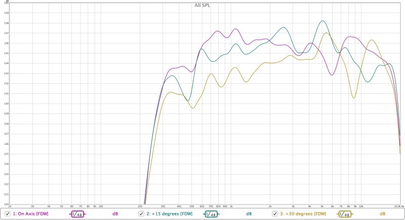
One could see that the dip is not consistent.
I also noticed that my CD is not exactly centered, there is like a milimiter offset 😀
I'll try to center it and improve the transition between the CD opening and the horn and see if that improves things 🙂
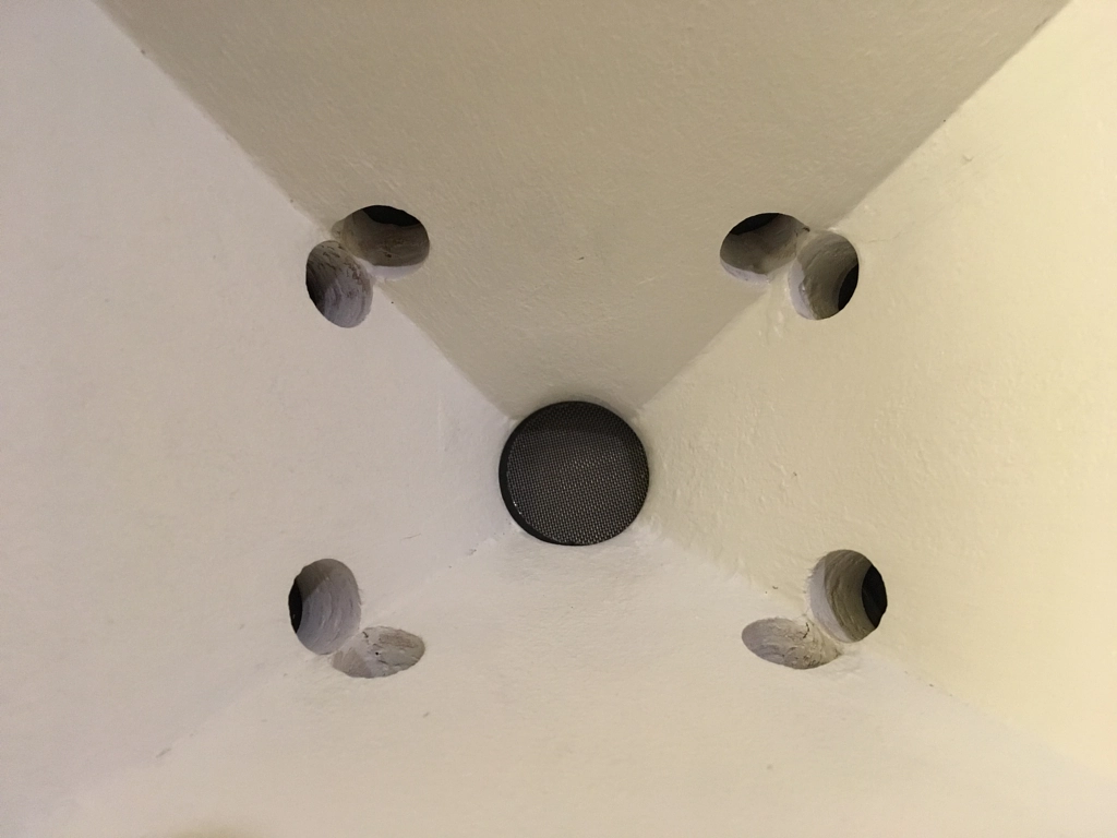
Thanks for all the help!
I tried to cover the midrange taps with tape, and indeed the dip disappeared!
If I move the holes towards the mouth of the horn, wouldn't similar dips lower in frequency appear?
I measured the response on axis, and at about 15 and 30 degrees
One could see that the dip is not consistent.
I also noticed that my CD is not exactly centered, there is like a milimiter offset 😀
I'll try to center it and improve the transition between the CD opening and the horn and see if that improves things 🙂
Thanks for all the help!
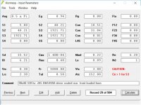
that is a good hint David,
Has anybody modelled the 4550 before?
I'm not sure what to use for Vrc and Lrc on the CD 😕
For the rest of the values, I use this (assuming it's a 5,5cm straight tube)
Ap1 5.10
Lpt 5.50
Vtc 27.80
Atc 5.10
Has anybody modelled the 4550 before?
I'm not sure what to use for Vrc and Lrc on the CD 😕
For the rest of the values, I use this (assuming it's a 5,5cm straight tube)
Ap1 5.10
Lpt 5.50
Vtc 27.80
Atc 5.10
- Home
- Loudspeakers
- Multi-Way
- Unity / Synergy Horn Build