This project is about taking the dipole principle as far as possible. I wanted to find out what happens if the mid and high frequency drivers are actually perfectly symmetrical and also perfectly aligned vertically. Vertical alignment is important because if you compensate the offset electronically for one side is will get worse for the other side and the reflection will no longer be an exact copy of the direct sound. I wanted to take away any clue the auditory system might use to locate the loudspeaker or determine that the sound is actually coming from a loudspeaker and not just simply ‘there’. Stored energy is another important clue our auditory system can use to determine that the sound is not real but reproduced so I also tried to keep the stored energy as low as possible.
The reason for posting this is to stress the importance of attaining a constant and smooth directivity. A true dipole is one way of obtaining a constant directivity but it is practically impossible to create a true full range dipole in the horizontal and vertical plane. However, creating a near full range dipole in the horizontal plane is possible. Due to the large amount of pictures and diagrams the story is split up into a couple of posts.
Form follows function:
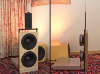
This is literally a top down design because it all started with my DIY ribbon dipole tweeter.
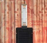
The details of this ribbon design can be found in this thread. The diagram that captures the essence of this design is the horizontal directivity of the filtered driver:
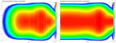
Near perfect dipole behaviour up to about 7kHz. This is how I came up with the name ’Totem of Tone’, in his thread ‘Beyond the Ariel’ Lynn Olson remarked that the region between 70Hz and 7kHz is where the tone lives. This system comes close to being a true dipole in the horizontal plane from 70Hz up to 7kHz and it looks a bit like an abstract totem pole, hence the name.
The ribbon driver also clearly fulfils the low stored energy requirement:
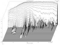
5ms time window, unsmoothed, 40dB vertical scale. As you can see not only is the decay very vast and clean, the response is also nearly flat within the operating band. It’s not easy to find a driver that can keep up with this.
The reason for posting this is to stress the importance of attaining a constant and smooth directivity. A true dipole is one way of obtaining a constant directivity but it is practically impossible to create a true full range dipole in the horizontal and vertical plane. However, creating a near full range dipole in the horizontal plane is possible. Due to the large amount of pictures and diagrams the story is split up into a couple of posts.
Form follows function:

This is literally a top down design because it all started with my DIY ribbon dipole tweeter.

The details of this ribbon design can be found in this thread. The diagram that captures the essence of this design is the horizontal directivity of the filtered driver:

Near perfect dipole behaviour up to about 7kHz. This is how I came up with the name ’Totem of Tone’, in his thread ‘Beyond the Ariel’ Lynn Olson remarked that the region between 70Hz and 7kHz is where the tone lives. This system comes close to being a true dipole in the horizontal plane from 70Hz up to 7kHz and it looks a bit like an abstract totem pole, hence the name.
The ribbon driver also clearly fulfils the low stored energy requirement:

5ms time window, unsmoothed, 40dB vertical scale. As you can see not only is the decay very vast and clean, the response is also nearly flat within the operating band. It’s not easy to find a driver that can keep up with this.
The B&G Neo10 seemed the obvious choice for handling the part below the ribbon. The Neo10 is a pretty unique, perfectly symmetric, magneplanar mid driver and it’s a shame it’s no longer available. The normalised horizontal directivity shows that it is a true dipole up to about 3kHz.
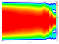
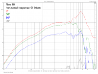
Directivity measurements were done in 5 degree steps from 0 to 90 degrees and mirrored horizontally. Here’s the unsmoothed response for several angles:
So, how low can we go? Placing the Neo10 in a baffle will raise the level, but how will this affect the directivity? To find out I measured the response and directivity of the Neo 10 with ‘wings’ of 2cm, 5cm and 10cm attached to it. Here’s the response comparison:
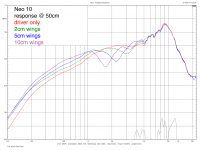
The low frequency output is indeed raised but there’s also a serious dip in the response. This is of course a worst case baffle design, straight baffle and symmetric placement but changing this will only mitigate the effects and not remove the fundamental issue. Look at the directivity comparison:
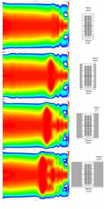
You can see the smooth directivity going down the drain as the baffle is widened. There’s no way you can EQ your way out of this as the response for the 2cm wings shows:
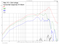
The on-axis dip becomes a peak off-axis, nothing you can do about it.
The minimum crossover frequency for the ribbon is 2.5kHz so I chose to use the Neo10 as is, without any baffle. Here’re some normalised polar plots of the naked Neo10:
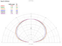
I still have to make some measurements of the current setup, but the system is so heavy (over 45kg) I cannot lift it on my own and I also have to construct a new turntable that can handle the load. To give you an idea how the Neo10 and the ribbon integrate I combined the normalised polar plots for the crossover frequency of 2.5kHz and an octave above and below:
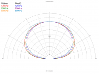
How’s that for constant directivity at the crossover?
The cumulative spectral decay measured at a distance of75cm vertically centred between the Neo10 and the ribbon:
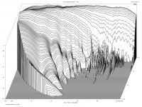
You can see that at this short distance the limited vertical dispersion already reduces the high frequencies but it is a very smooth and quick decay. The time window is just 3ms but the vertical scale is 40dB.
The harmonics measured at 50cm 1/12oct smoothing, vertical position mid ribbon:
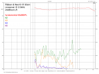
The scale for the harmonics is on the right, it is in percent with 1% full scale. Very acceptable performance but there is room for improvement. Reducing distortion to a minimum is a matter of finding the right combination of ribbon thickness, tension and corrugation and as such is the subject of further experiments.

Directivity measurements were done in 5 degree steps from 0 to 90 degrees and mirrored horizontally. Here’s the unsmoothed response for several angles:

So, how low can we go? Placing the Neo10 in a baffle will raise the level, but how will this affect the directivity? To find out I measured the response and directivity of the Neo 10 with ‘wings’ of 2cm, 5cm and 10cm attached to it. Here’s the response comparison:

The low frequency output is indeed raised but there’s also a serious dip in the response. This is of course a worst case baffle design, straight baffle and symmetric placement but changing this will only mitigate the effects and not remove the fundamental issue. Look at the directivity comparison:

You can see the smooth directivity going down the drain as the baffle is widened. There’s no way you can EQ your way out of this as the response for the 2cm wings shows:

The on-axis dip becomes a peak off-axis, nothing you can do about it.
The minimum crossover frequency for the ribbon is 2.5kHz so I chose to use the Neo10 as is, without any baffle. Here’re some normalised polar plots of the naked Neo10:

I still have to make some measurements of the current setup, but the system is so heavy (over 45kg) I cannot lift it on my own and I also have to construct a new turntable that can handle the load. To give you an idea how the Neo10 and the ribbon integrate I combined the normalised polar plots for the crossover frequency of 2.5kHz and an octave above and below:

How’s that for constant directivity at the crossover?
The cumulative spectral decay measured at a distance of75cm vertically centred between the Neo10 and the ribbon:

You can see that at this short distance the limited vertical dispersion already reduces the high frequencies but it is a very smooth and quick decay. The time window is just 3ms but the vertical scale is 40dB.
The harmonics measured at 50cm 1/12oct smoothing, vertical position mid ribbon:

The scale for the harmonics is on the right, it is in percent with 1% full scale. Very acceptable performance but there is room for improvement. Reducing distortion to a minimum is a matter of finding the right combination of ribbon thickness, tension and corrugation and as such is the subject of further experiments.
Using the Neo10 without any baffle requires that the low cutoff is raised, although the datasheet suggests 250Hz-350Hz for single driver use I found that 400Hz 24dB/oct LR is required to keep the distortion down at high levels. This immediately rules out using an H-frame and or subwoofer drivers for the bass. To maintain dipole behaviour up to 400Hz the baffle must be as small as possible and a driver with excellent low-mid quality and large excursion capability is required. I chose the AudioTechnology Flexunit 10C77 25 10 KAP. This is a 10” driver with a 77mm kapton-aluminium voice coil former (kapton for the linear part). The single sided linear Xmax is 8mm, peak excursion is 21mm.
The baffle is seriously over-engineered, 4 layers of 6mm aircraft quality birch plywood and 3 layers of 3mm lead sheet bonded with epoxy resin glue. Total thickness is 36mm. It is very stiff, extremely heavy (15kg for the baffle alone) and has good internal damping. I used aircraft quality plywood not so much for the stiffness but because it is fault free and you get perfect striping on the sides.
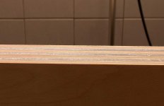
The drive units are 8.6kg each, this results in a total weight for the baffle and drivers of 32.2kg. The moving mass for the two drivers is 109g, about 60% of a single 10” Seas as used in the Linkwitz LX521, combined with the high mass of the baffle and drivers this results in very little baffle movement even when playing music at high levels.
To provide the necessary support and counterweight for the baffle I came up with the following solution, a 550mm x 300mm x 10mm sheet of aluminium:
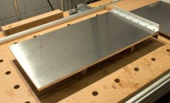
4.5kg of aluminium to provide support and act as heatsink and mounting platform for amplifiers and filter. The wired amplifiers and filter:
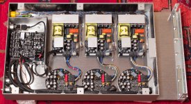
A Hypex DLCP DSP and 3 NCore400 amplifiers each with its own power supply.
Yes! Oh horror, I use the analog input of the Hypex DLCP. I have a lot of 5.1 material on DVD, DVD Audio, SACD and Blu-ray and it’s near to impossible to decode all these formats and output them as separate S/PDIF streams.
To figure out for myself if the DLCP AD/DA conversion was noticeable (and as a tool for further experiments) I build my ‘Black Box DLCP’:
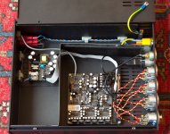
Wired to strictly to AES48 specs. RF input filter directly on chassis connector, pin 1 connected to chassis directly at the connector.
My Oppo BDP-105 has balanced and unbalanced outputs so I could compare the direct signal and the signal passed through the DLCP with neutral settings by switching input on my preamp. Of course the level was matched within 0.1dB otherwise all bets are off. I was unable to detect any difference so I decided to just use the analog inputs and be done with it, after all the AD converter is very good and the overall implementation of the DLCP with it’s 9 local regulators seems to be very well thought out.
Rear view of the system:
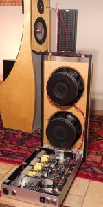
The power supply and amplifier closest to the filter are for the Neo10, as this power supply has very little to do the DLCP is connected to the aux out of this power supply. The amp closest to the baffle drives the two AT drivers, the wires of each driver are connected at the Ncore. The large ventilation hole in the pole piece of the driver is also clearly visible through the foam cover.
In the background you see my previous system, the Linkwitz Orion 3.2.1 with Thor subwoofer.
The bottom of the plate with the series resistors for the ribbon and Neo10:
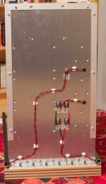
Lots of M5 bolts to connect the plate to the baffle. There’s hardly any movement in the baffle, you have to use considerable force to even notice that it is not bolted to the floor.
The bottom octave and below are handled by closed box subwoofers. These are essentially Linkwitz Thor subs with digital filtering. I didn’t replicate the Thor filters in DSP but started from scratch, I found that applying a Linkwitz transform by the book results in a bump in the response so I tweaked the parameters a bit to get a flat response. The subs have their own NCore400 amplifier and power supply:
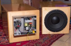
The amp-on signal for the sub comes from the DLCP, all amps will switch on when the DLCP startup is complete, this provides for a click and thump free startup and shutdown.
The baffle is seriously over-engineered, 4 layers of 6mm aircraft quality birch plywood and 3 layers of 3mm lead sheet bonded with epoxy resin glue. Total thickness is 36mm. It is very stiff, extremely heavy (15kg for the baffle alone) and has good internal damping. I used aircraft quality plywood not so much for the stiffness but because it is fault free and you get perfect striping on the sides.

The drive units are 8.6kg each, this results in a total weight for the baffle and drivers of 32.2kg. The moving mass for the two drivers is 109g, about 60% of a single 10” Seas as used in the Linkwitz LX521, combined with the high mass of the baffle and drivers this results in very little baffle movement even when playing music at high levels.
To provide the necessary support and counterweight for the baffle I came up with the following solution, a 550mm x 300mm x 10mm sheet of aluminium:

4.5kg of aluminium to provide support and act as heatsink and mounting platform for amplifiers and filter. The wired amplifiers and filter:

A Hypex DLCP DSP and 3 NCore400 amplifiers each with its own power supply.
Yes! Oh horror, I use the analog input of the Hypex DLCP. I have a lot of 5.1 material on DVD, DVD Audio, SACD and Blu-ray and it’s near to impossible to decode all these formats and output them as separate S/PDIF streams.
To figure out for myself if the DLCP AD/DA conversion was noticeable (and as a tool for further experiments) I build my ‘Black Box DLCP’:

Wired to strictly to AES48 specs. RF input filter directly on chassis connector, pin 1 connected to chassis directly at the connector.
My Oppo BDP-105 has balanced and unbalanced outputs so I could compare the direct signal and the signal passed through the DLCP with neutral settings by switching input on my preamp. Of course the level was matched within 0.1dB otherwise all bets are off. I was unable to detect any difference so I decided to just use the analog inputs and be done with it, after all the AD converter is very good and the overall implementation of the DLCP with it’s 9 local regulators seems to be very well thought out.
Rear view of the system:

The power supply and amplifier closest to the filter are for the Neo10, as this power supply has very little to do the DLCP is connected to the aux out of this power supply. The amp closest to the baffle drives the two AT drivers, the wires of each driver are connected at the Ncore. The large ventilation hole in the pole piece of the driver is also clearly visible through the foam cover.
In the background you see my previous system, the Linkwitz Orion 3.2.1 with Thor subwoofer.
The bottom of the plate with the series resistors for the ribbon and Neo10:

Lots of M5 bolts to connect the plate to the baffle. There’s hardly any movement in the baffle, you have to use considerable force to even notice that it is not bolted to the floor.
The bottom octave and below are handled by closed box subwoofers. These are essentially Linkwitz Thor subs with digital filtering. I didn’t replicate the Thor filters in DSP but started from scratch, I found that applying a Linkwitz transform by the book results in a bump in the response so I tweaked the parameters a bit to get a flat response. The subs have their own NCore400 amplifier and power supply:

The amp-on signal for the sub comes from the DLCP, all amps will switch on when the DLCP startup is complete, this provides for a click and thump free startup and shutdown.
So, was it worth the effort? Yes, definitely yes! I’ve been listening to this system for over 6 months now and I haven’t yet detected anything problematic, as far as I’m concerned it is a blameless loudspeaker. The nearly constant horizontal directivity and perfect dipole symmetry (at least above 400Hz) results in an exceptionally focused and stable stereo image. Because the system is so narrow at the top it also does not stand in the way of it’s own back-wave reflection, I think this is very important for a dipole. A wide baffle will cast a shadow so to speak which will make it possible for your auditory system to (more easily) detect its position.
Yes, the system is horribly inefficient but the amplifiers and power supplies are all very efficient so the total power consumption in rest is just above 100W which is not bad for a system with a peak power of well over 3kW. The enormous peak power capability does provides horn like dynamics and ease of presentation. The operating temperature is somewhere between 30 and 40 degrees Celsius depending on output power. The system is very, very quiet, you have to press your ear against the Neo10 to be able to hear a faint noise. No hum, no clicks, no pop or crackle. The system is also free of any mechanical noise (humming or whistling).
So where’s the catch? Well, it won’t do an orchestra at full concert level despite the enormous amount of power available. The maximum SPL I measured on the my listening couch (3m distance, with acceptable distortion) was about 103dB which is more than enough for me and it also is enough for SMPTE RP 200, 83dBSPL average at the listening position with 20dB headroom (83dBSPL = -20dBFS). The limited vertical dispersion requires a minimum listening distance of 3m for proper integration of low,mid and high frequencies and sufficient high frequency dispersion. The system is certainly not child or pet proof and I would expect the WAF to be close to 0. And then there’s the cost, this particular implementation with the AT drivers and Ncore amps is very expensive but even with other amps and drivers this kind of system will never be cheap.
To evaluate the quality of the stereo imaging I came up with the following setup:
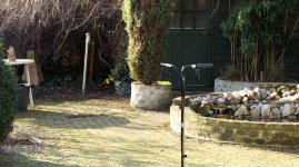
A little winter audio scene in my backyard. On the left on the table is a mechanical metronome, the little pond has three little waterfalls and what you don’t see is the freeway in the background. The freeway is behind 200m of trees and running parallel to the stereo axis resulting in a diffuse sound ‘carpet’ filling the stereo image. The two cardioid microphones are amplified using a simple Mackie mixer. I tried several methods, the picture shows NOS, and found that X/Y works best with the dipoles. The quality of the reproduction is quite stunning, especially the way the diffuse background noise is rendered. The metronome is rendered with pinpoint accuracy, it sounds as if you could walk over and grab it. The little waterfalls are also very realistic, just ‘there’.
As you might imagine I’m very happy with this system, it does everything that I hoped for and then some. It has definitely convinced me of the importance of constant directivity, and in the case of dipoles of dipole symmetry. The fact that the measurement results are all very good and can all be presented without any smoothing applied also gives me piece of mind, I no longer feel the need to listen for defects in the reproduction, now I just listen to the music.
I hope this short report results in more people paying attention to the directivity of loudspeakers whether it be dipoles, omnipoles, cardioids or waveguides/horns, it really is worth the effort. Maybe the ‘directivity plot’ should be renamed to ‘spatial distortion plot’. Spatial distortion has a nice ring to it and the term more accurately describes what’s going on; irregular directivity will distort the stereo space (image).
regards,
Gerrit
Yes, the system is horribly inefficient but the amplifiers and power supplies are all very efficient so the total power consumption in rest is just above 100W which is not bad for a system with a peak power of well over 3kW. The enormous peak power capability does provides horn like dynamics and ease of presentation. The operating temperature is somewhere between 30 and 40 degrees Celsius depending on output power. The system is very, very quiet, you have to press your ear against the Neo10 to be able to hear a faint noise. No hum, no clicks, no pop or crackle. The system is also free of any mechanical noise (humming or whistling).
So where’s the catch? Well, it won’t do an orchestra at full concert level despite the enormous amount of power available. The maximum SPL I measured on the my listening couch (3m distance, with acceptable distortion) was about 103dB which is more than enough for me and it also is enough for SMPTE RP 200, 83dBSPL average at the listening position with 20dB headroom (83dBSPL = -20dBFS). The limited vertical dispersion requires a minimum listening distance of 3m for proper integration of low,mid and high frequencies and sufficient high frequency dispersion. The system is certainly not child or pet proof and I would expect the WAF to be close to 0. And then there’s the cost, this particular implementation with the AT drivers and Ncore amps is very expensive but even with other amps and drivers this kind of system will never be cheap.
To evaluate the quality of the stereo imaging I came up with the following setup:

A little winter audio scene in my backyard. On the left on the table is a mechanical metronome, the little pond has three little waterfalls and what you don’t see is the freeway in the background. The freeway is behind 200m of trees and running parallel to the stereo axis resulting in a diffuse sound ‘carpet’ filling the stereo image. The two cardioid microphones are amplified using a simple Mackie mixer. I tried several methods, the picture shows NOS, and found that X/Y works best with the dipoles. The quality of the reproduction is quite stunning, especially the way the diffuse background noise is rendered. The metronome is rendered with pinpoint accuracy, it sounds as if you could walk over and grab it. The little waterfalls are also very realistic, just ‘there’.
As you might imagine I’m very happy with this system, it does everything that I hoped for and then some. It has definitely convinced me of the importance of constant directivity, and in the case of dipoles of dipole symmetry. The fact that the measurement results are all very good and can all be presented without any smoothing applied also gives me piece of mind, I no longer feel the need to listen for defects in the reproduction, now I just listen to the music.
I hope this short report results in more people paying attention to the directivity of loudspeakers whether it be dipoles, omnipoles, cardioids or waveguides/horns, it really is worth the effort. Maybe the ‘directivity plot’ should be renamed to ‘spatial distortion plot’. Spatial distortion has a nice ring to it and the term more accurately describes what’s going on; irregular directivity will distort the stereo space (image).
regards,
Gerrit
Congratulations Gerrit! Excellent writeup of your dipoles. Planars and dsp are my favourite things too!
Whre and how do you cross to monopole subs?
Whre and how do you cross to monopole subs?
Congratulations Gerrit! Excellent writeup of your dipoles. Planars and dsp are my favourite things too!
Whre and how do you cross to monopole subs?
Thank you 🙂
DSPs are not to everyones taste but I think this kind of system requires the use of DSP, yes you probably could do it analog but this would be a very tedious affair
and it is not certain that this will give the better overall result.
The subs are crossed at 40Hz 24dB/oct LR filters, they really only do the bottom octave and below (-3dB @20hz, -8dB @10Hz) There's a room node around 40Hz, suppressing this peak also reduces the excursion of the dipole woofers. The house is build with bricks and concrete so there is significant room gain which also result in reduced excursion requirements.
regards,
Gerrit
I think the project deserves a:

Thank you 🙂
This seems seriously legit
Which channel is the limiting factor in overall SPL capability?
Thanks 🙂
The SPL is limited by the tweeter distortion and peak current capability of the NCore amp for the tweeter. It's a shame that there is no level metering on the DLCP, it could very well be that the DLCP is also running out of bits at (very) high levels. The good thing is that it sounds very clean right up to the maximum level, you cannot hear that you are close to the maximum.
regards,
Gerrit
Excellent engineering and professional construction.
Edge diffraction effects from the sharp magnet/steel ribbon pole pieces are sometimes managed by radius quarter rounds. RAAL ribbons use a saw-tooth diffuser baffle plate. A beveled piece of wool felt attached to the pole steel has also been used for reducing diffraction. Careful listening tests often demonstrates the advantage of ribbon edge diffraction control.
Edge diffraction effects from the sharp magnet/steel ribbon pole pieces are sometimes managed by radius quarter rounds. RAAL ribbons use a saw-tooth diffuser baffle plate. A beveled piece of wool felt attached to the pole steel has also been used for reducing diffraction. Careful listening tests often demonstrates the advantage of ribbon edge diffraction control.
Excellent engineering and professional construction.
Edge diffraction effects from the sharp magnet/steel ribbon pole pieces are sometimes managed by radius quarter rounds. RAAL ribbons use a saw-tooth diffuser baffle plate. A beveled piece of wool felt attached to the pole steel has also been used for reducing diffraction. Careful listening tests often demonstrates the advantage of ribbon edge diffraction control.
Thank you 🙂
I don't think there's much edge diffraction, the directivity is very smooth and the unsmoothed frequency response filtered ribbon doesn't show a dip becoming a peak off-axis as was the case with the Neo10 experiments:
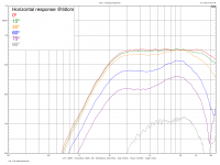
Or could the small irregularities in the response be caused by diffraction effects?
With my first ribbon experiment I used foam triangles to 'take the edge of the baffle':
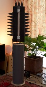
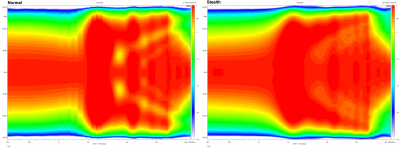
I called them 'stealth triangles', the normalised directivity comparison shows that there's certainly an improvement:
With the minimal ribbon there hardly is any baffle left but I could try placing little felt triangles on the magnets. Another option is to make the ribbon just a little bit smaller, 18mm in stead of 19mm, and place felt 'diamonds' on the magnets in the gap.
Any ideas as to what would be worth trying?
regards,
Gerrit
Dipole radiation pattern wins over edge diffractions below the dipole null, which lies around 10kHz. I expect no/minimal benegit from "edge treatment" but perhaps it is worth an experiment?
The previos model had much wider baffle and then dipole null was perhaps around 3-4kHz (12-15cm wide?)
The previos model had much wider baffle and then dipole null was perhaps around 3-4kHz (12-15cm wide?)
Last edited:
Dipole radiation pattern wins over edge diffractions below the dipole null, which lies around 10kHz. I expect no/minimal benegit from "edge treatment" but perhaps it is worth an experiment?
The previos model had much wider baffle and then dipole null was perhaps around 3-4kHz (12-15cm wide?)
Here're the response curves for the 'stealth' ribbon:
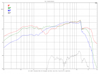
The ribbon is 1.4cm wide and 40cm long the steel plate is 20cm wide and 60cm high. It looks like it's a true dipole below 600Hz, the cutoff is 800Hz so it's not a true dipole in the operating band.
regards,
Gerrit
Dipole peak and null are quite diffuse in those measurements, is that caused by the stealth wings? I remember someone at diyaudio "masked" it totally with a felt baffle.
What is the distance in these measurements, obviously 1m or like that?
What is the distance in these measurements, obviously 1m or like that?
Dipole peak and null are quite diffuse in those measurements, is that caused by the stealth wings? I remember someone at diyaudio "masked" it totally with a felt baffle.
What is the distance in these measurements, obviously 1m or like that?
I don't recall exactly but it is either 1m or 70cm. I use a distance of 50cm only for small drivers like my minimal ribbon or the Neo10.
regards,
Gerrit
Agree!
Thank you 🙂
Recently I thought I noticed some distortion in the mid but it turned out to be the wires for the mid end tweeter rattling in the aluminium profiles. To fix this I filled the profiles with sand. I mention this as a reminder to always check your loudspeakers with a sine sweep for any mechanical noise like rattling.
regards,
Gerrit
An externally hosted image should be here but it was not working when we last tested it.
i´ve found that these will express themselves in distortion graph too
An externally hosted image should be here but it was not working when we last tested it.
i´ve found that these will express themselves in distortion graph too
With the Neo10 there's no other option, soldering will void the warranty. For the AT woofers I used gold plated Mundorf fastons with Van Den Hul 'The Solution' for improved contact. The fastons are very tight so I don't think this is a potential problem. These connectors are used in cars for decennia in the most extreme conditions and rarely cause any problems.
regards,
Gerrit
- Status
- Not open for further replies.
- Home
- Loudspeakers
- Multi-Way
- The Totem of Tone, an active 3-way dipole and active subwoofer