Hello everyone,
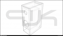
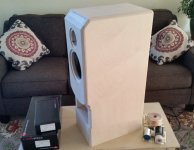
For the past few weeks I have been working on building an enclosure for my ZRT 2 way kit. I decided to do something a little different and had a custom enclosure designed by Peter Kulicki of PWK Designs; the goal of which was to extend the bass shelf over a sealed design while not going to a full size tower. I gave the information on the Kit/Crossover, as well as a desired maximum external size (keeping the baffle geometry similar to the Zaph Kit), and let him decide what the best configuration would be. I know this is somewhat risky compared to building with the standard enclosure options for the 2 way kit, but I just wanted to see If I could get something fairly small that extends lower that the sealed configuration.
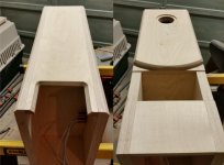
I received the design, and decided to add 5 inches to the bottom of the enclosure to house the crossover network as well as allow for a modular rear panel for binding posts and tweeter attenuation selector. Other than that I have increased the side wall thickness from .75" to 1.25" (double stack 5/8" maple ply), and increased the baffle thickness from .75 to 1.375 (double stack, 3/4" + 5/8" maple ply). External dimensions are 10" X 15" X 30".
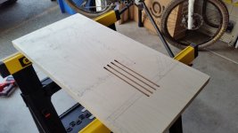
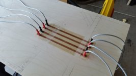
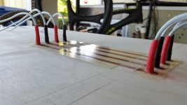
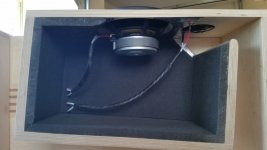
Due to the design at hand I had to figure out how to get the speaker cables up through the horn/port. I ended up using 1/4" 101 copper bar laid into 1/4" slots in the left side wall, the bar has Supra classic 2.5 (13 AWG) wire soldered on both ends. The bars were then sealed into the side walls with a clear epoxy resin, it didn't turn out great, some air bubbles were entrapped, but I am sure it will function well and prevent oxidation/discoloration.
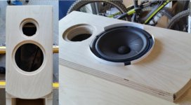
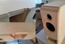
The bevels on the sides of the baffle are 1/2" to keep the same 9" baffle width as the Zaph enclosures, as with the thicker side panels the enclosures are now 10" wide. The tweeter sits 1.65" lower than on the Zaph Audio enclosure, so I will create a large bevel to match the distance from the tweeter to the top edge of the baffle on the Zaph enclosure.
The side panels received two layers of Damplifier Pro inside the compression chamber, while the top, back and bottom walls of the compression chamber received a single layer. Two layers of open cell acoustic foam were applied to the back of the compression chamber directly behind the mid woofer, while all other walls received a single layer.
I still have a few more things to do before I glue on the right side, such as add the 45 deg. panels in the corners of the horn/port. Also, I need to cut out the back panel for the binding post plate.
All in all, for my first build things are going well and I am having fun and learning a lot! Hopefully the pictures I have attached work.
For the past few weeks I have been working on building an enclosure for my ZRT 2 way kit. I decided to do something a little different and had a custom enclosure designed by Peter Kulicki of PWK Designs; the goal of which was to extend the bass shelf over a sealed design while not going to a full size tower. I gave the information on the Kit/Crossover, as well as a desired maximum external size (keeping the baffle geometry similar to the Zaph Kit), and let him decide what the best configuration would be. I know this is somewhat risky compared to building with the standard enclosure options for the 2 way kit, but I just wanted to see If I could get something fairly small that extends lower that the sealed configuration.
I received the design, and decided to add 5 inches to the bottom of the enclosure to house the crossover network as well as allow for a modular rear panel for binding posts and tweeter attenuation selector. Other than that I have increased the side wall thickness from .75" to 1.25" (double stack 5/8" maple ply), and increased the baffle thickness from .75 to 1.375 (double stack, 3/4" + 5/8" maple ply). External dimensions are 10" X 15" X 30".
Due to the design at hand I had to figure out how to get the speaker cables up through the horn/port. I ended up using 1/4" 101 copper bar laid into 1/4" slots in the left side wall, the bar has Supra classic 2.5 (13 AWG) wire soldered on both ends. The bars were then sealed into the side walls with a clear epoxy resin, it didn't turn out great, some air bubbles were entrapped, but I am sure it will function well and prevent oxidation/discoloration.
The bevels on the sides of the baffle are 1/2" to keep the same 9" baffle width as the Zaph enclosures, as with the thicker side panels the enclosures are now 10" wide. The tweeter sits 1.65" lower than on the Zaph Audio enclosure, so I will create a large bevel to match the distance from the tweeter to the top edge of the baffle on the Zaph enclosure.
The side panels received two layers of Damplifier Pro inside the compression chamber, while the top, back and bottom walls of the compression chamber received a single layer. Two layers of open cell acoustic foam were applied to the back of the compression chamber directly behind the mid woofer, while all other walls received a single layer.
I still have a few more things to do before I glue on the right side, such as add the 45 deg. panels in the corners of the horn/port. Also, I need to cut out the back panel for the binding post plate.
All in all, for my first build things are going well and I am having fun and learning a lot! Hopefully the pictures I have attached work.
No pictures have appeared, but I must say you are very detailed oriented especially in light of the fact this is your first time build.
Had you heard a standard version of this design before you decided to build ?
Also, Am I to understand you went with a larger (than sealed version) enclosure, yet not to the full size vented version?
Had you heard a standard version of this design before you decided to build ?
Also, Am I to understand you went with a larger (than sealed version) enclosure, yet not to the full size vented version?
I see that the pictures that I attached did not work, I will see what I can do when I get home from work this evening.
To answer your questions Scott, I have not heard a ZRT design in any of the configurations. Im my area I didnt have much of a chance to listen to options before purchase, so after a lot of research I went with the ZRT. Besides car stereo and a little Focal 2.1 setup for the laptop I dont have much experience with high end home stereo, so I won't have much to compare these too.
The goal was to improve the bass shelf withought going to a full size tower, I believe that what Pete came up with is referred to as a folded horn (horn starts in upper front corner and wraps around the top/back/bottom with a 5 degree taper.
Hopefully I will be able to get some pics uploaded tonight to give a better idea of what is going on.
IMHO, you took a risk in modifying the design in some sensible areas. Moreover doing so with an expensive design.
First: changing baffle size (width, and driver positions from the top), means that diffraction related FR will change. You should have at least simulated it before building the cabs for example with BDS (free SW, requires excel).
Second: bass loading. I'm not into horns so I cannot comment on the viability of the solution chosen, but one of the plus of the SS midbass is the bass, and the tower version is designed to take advantage of that. Again, a horn should have been simulated correctly before. What's the tuning obtained?
Ralf
Hi Ralf, thanks for the input. I agree that I have taken a risk by going with unproven design, but I have also tried to mitigate the risk by keeping the same baffle geometry as the Zaph enclosure. The design above is 10" wide as apposed to the 9" on the zaph enclosure, so I will do a 1/2" 45 degree bevel on each side to get the effective baffle width down to 9". Due to the location of the start of the horn, the tweeter location is 4.65" down from the top instead of the 3" on the zaph enclosure, I will account for this by adding a 1.65" 45 deg. bevel at the top above the tweeter.
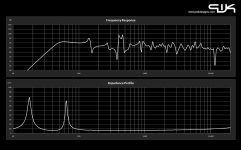
You will see that I deviated from the mid/woofer location that was recommended in the designs that were sent by Pete, I did this in order to keep the baffle geometry as similar to a standard ZRT enclosure as possible. Pete is well known in the car audio world for designing sub woofer enclosures, and simulates the designs in a program that he wrote/developed. I ordered the "graph pack" when I placed my order, I have attached the simulated Frequency Response and Impedance Profile plots.
He has also done a fair bit of experimentation and design in the realm of two channel stereo systems, ranging from bass reflex, full range horns and dipoles from what I have seen. Here is a link to a build that first got me thinking about having a custom design made (Sculpture 101 HT Monitor ).
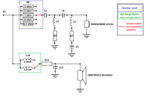
With the changes made to the design I have decided that it would probably be best to incorporate the tweeter level/attenuation (R8) as well as the mid-range baffle step compensation (L10). The planned circuit is also attached. The additional resistors and inductor will be selected via the rear panel, so I should be able to adjust for listening preferences as well as for room size or near field listening.
You will see that I deviated from the mid/woofer location that was recommended in the designs that were sent by Pete, I did this in order to keep the baffle geometry as similar to a standard ZRT enclosure as possible. Pete is well known in the car audio world for designing sub woofer enclosures, and simulates the designs in a program that he wrote/developed. I ordered the "graph pack" when I placed my order, I have attached the simulated Frequency Response and Impedance Profile plots.
He has also done a fair bit of experimentation and design in the realm of two channel stereo systems, ranging from bass reflex, full range horns and dipoles from what I have seen. Here is a link to a build that first got me thinking about having a custom design made (Sculpture 101 HT Monitor ).
With the changes made to the design I have decided that it would probably be best to incorporate the tweeter level/attenuation (R8) as well as the mid-range baffle step compensation (L10). The planned circuit is also attached. The additional resistors and inductor will be selected via the rear panel, so I should be able to adjust for listening preferences as well as for room size or near field listening.
Attachments
Now that one of the enclosures is nearly completed and the end of fabrication is in sight (next one should go more quickly I am thinking), I am starting to think about other items for my setup.
I will need a source, Preamp, and Amp/Amps. For the source I am leaning towards the Oppo BDP105, but I am open to suggestions. For the longest time I was looking at Emotiva gear, with a XSP-1 Pre and XPA-1L monoblocks, but now I have the DIY bug and am looking into possibly doing some Hypex nCore 400's.
The hard part to get over would be that the nCore's would cost more to build than I could get the XPA-1L's for right now, but then again there is the cool factor of having a DIY amp. With the nCore's I would probably do monoblocks and make them so that they fit in or under my speakers, keeping speaker wire lengths to a minimum and also cleaning up the install and increasing the WAF.
Any words of wisdom on selecting the rest of the gear that I need to listen to these?
hello All,
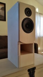
I have been working away on the first enclosure and have nearly completed the first one; I have gotten it to a stage where it can at least be tested. I borrowed an Onkyo receiver from a friend and have listened to the single speaker a moderate levels for several hours.
At first I was a bit disappointed in the bass output, though overall the sound was great, it was lacking in the lower notes. After several hours of listening, however, the bass has improved dramatically, and the overall package is sounding good. Granted, this is only a single speaker, but so far so good. As of right now I am just using the stock binding posts/terminals as well as the stock crossover (7 ohm resistor on the tweeter circuit and 2.7mH inductor on the woofer). I will probably still buy the other resistors and inductors just to have options, but as is the speakers is to my linking, and I imagine things will only improve when I add the other.
Attachments
For the longest time I was looking at Emotiva gear, with a XSP-1
Pre and XPA-1L monoblocks, but now I have the DIY bug and am
looking into possibly doing some Hypex nCore 400's.
Emotiva gear looks good and affordable. One thing bugs me, XPA-1L
specs say 250W/8 0hm and 500W/4 ohm. Being a class A/B amp and
with only 450 VA transformer, I am not sure where the 500 W could
be coming from. Certainly not from the default transformer.
Very nice build and I have to say you are very meticulous and excellent craftsmanship. Did PWK simulate the design to arrive at the geometry provided - and can you share those sims? I have to agree with the other posts that a design like this with a custom XO and baffle in a sealed box may not translate to this design, really technically a big vent reflex (BVR) rather than true back loaded horn. If you haven't bought the parts for the XO yet (and I believe Zaph usually goes all out with XO's that can cost quite a bit) you may want to bi amp it and use a miniDSP or similar to tune and tweak the XO settings to see if the stock Zaph one will work. You can dial in the Zaph XO as if you had one passively. If you don't have miniDSP and biamps already check out a neat trick to do it for no cost in mono to test it all out here: http://www.diyaudio.com/forums/multi-way/261506-using-stereo-sound-card-create-mono-2-way-active-crossover.html
If you are interested, post some key dimensions of your speaker like baffle width height box depth chamber volume, throat area, mouth area, and horn run length. It is easy to sim this in AkAbak as a BVR. The sim will give you a good indication of the rough XO needed as well as the all pass delay you will need to time align the tweeter and woofer and vent output.
If you are interested, post some key dimensions of your speaker like baffle width height box depth chamber volume, throat area, mouth area, and horn run length. It is easy to sim this in AkAbak as a BVR. The sim will give you a good indication of the rough XO needed as well as the all pass delay you will need to time align the tweeter and woofer and vent output.
Last edited:
Baffle dimensions are as follows:
Width: 9" effective (edges of bevel on baffle front)
Height: 17.67" effective (from edge of bevel down on baffle front)
Tweeter distance from top: 3" effective (edge of bevel on baffle front)
Woofer distance from top: 9" effective (edge of bevel on baffle front)
Horn Dimensions:
Throat Area: 1.86" x 7.5" = 13.95 in^2
Mouth Area: 5" x 7.5" =37.5 in^2
Horn Taper: 5 deg.
Chamber Volume: 288.36 in^3 (4.725 L)
Horn run Length:
internal wall: 35.85"
external wall: 49.39"
median distance: 42.62"
Hi,
A lot of time and effort and good building skills to make things worse.
You cannot help yourself fiddling can you ? Not good for a first build.
https://sites.google.com/site/undefinition/diy-mfaq2
Bevels don't change baffle widths, though your big bevel on the
top probably has a bit less than half the effect you imagine.
(Bevels reduce higher ripples, not the basic ripple).
I can't comment on boxes designed with bespoke software that
may or may not be right, but you've changed the supplied design
anyway, so no point other than saying I simply don't like it.
Its not a horn in any sense, IMO it will have poor bass.
Which is a tour de force of the ZRT, sealed or vented.
FWIW the design of low colouration cabinets as opposed
to cheap and simple has never been resolved, and likely
never will be, it is an area imagination can be worthwhile.
rgds, sreten.
17.7 liters helps some but note that ZRT bass reflex tower used 37 liters. I want to confirm that driver is Scanspeak 18w8531g. The Vas on that is 2 cu ft and to put that driver in about half a cubic ft will really hurt the bass output since this is a BVR and not a BLH. Even if it were a BLH the length of the horn is about 1m so the freq will be no lower than 80Hz. Was 80Hz the low freq you were looking for? It seems awfully high given the fs of 28Hz.
The expected frequency response and impedance plot is attached on the first page, to my untrained eye it appears to go down to 50Hz before dropping off. So far the limited listening of the single enclosure has revealed excellent bass output, and its only getting better during break in.
Hi,
Its poor reworking of the original design, that much is for sure.
You can't do better than seled in less than a good sealed
volume, and you can't do better than vented in less than
a good vented volume, both are very self evident.
That a folded option exists between sealed and vented
volumes is utter nonsense, and here it is nonsense.
You can pay to be deluded, and seduced by complexity.
rgds, sreten.
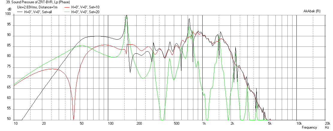
Sim of ZRT BVR
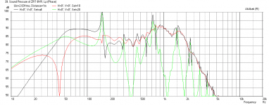
Here is my simulation of your speaker. Although it does have bass down to about 50Hz, I think you are going to have problems with a lot of frequency dips in the mid-bass. This is a simple model of the vent without the turns, so it will let a little more HF's out, but the overall geometry indicates that it is far from an ideal system. I have placed the speaker on the floor, 5ft away from a back wall for the purposes of this sim. The floor bounce from the vent mouth is causing most of the problems. Raising it up on stands helped a little but did not fix it. I did not enter the XO circuit - just a simple BW -24dB/oct LPF and HPF was applied for the purposes of effecting a 4th order XO at the 1700Hz location as suggested by Zaph's design (which was actually -12dB/oct).
Here is the LF unit with a 1700Hz -24dB/oct LPF XO:
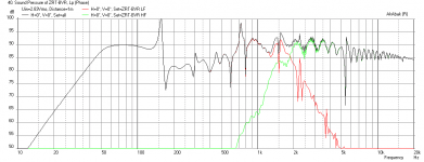
Here is the combined LF and HF unit with the 1700Hz XO:
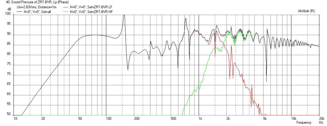
I don't know what else to tell you other than good luck getting it to behave flat like Zaph's original:
Here is my simulation of your speaker. Although it does have bass down to about 50Hz, I think you are going to have problems with a lot of frequency dips in the mid-bass. This is a simple model of the vent without the turns, so it will let a little more HF's out, but the overall geometry indicates that it is far from an ideal system. I have placed the speaker on the floor, 5ft away from a back wall for the purposes of this sim. The floor bounce from the vent mouth is causing most of the problems. Raising it up on stands helped a little but did not fix it. I did not enter the XO circuit - just a simple BW -24dB/oct LPF and HPF was applied for the purposes of effecting a 4th order XO at the 1700Hz location as suggested by Zaph's design (which was actually -12dB/oct).
Here is the LF unit with a 1700Hz -24dB/oct LPF XO:
Here is the combined LF and HF unit with the 1700Hz XO:
I don't know what else to tell you other than good luck getting it to behave flat like Zaph's original:
Attachments
Last edited:
Hey guys, I thank you for bringing up these issues, and I admit that the frequency response that I received from Pete was not what I was expecting.
I started this project first with a little bit of research on DIY speakers, which after a while led me to the ZRT kit. I read a lot of good things about the design and decided to purchase the Kit, with the intention of building them up in the sealed configuration.
Some time later I decided to ask Pete if he could come up with something that was in between the size of the sealed and ported options that offered a bit more low end than the sealed version. I gave him my maximum external dimensions and he responded that given the available internal volume, he should be able to come up with something that would satisfy my want for better low end. In the car audio word Pete is well known for developing enclosures for subs that are leagues above the generic enclosures that subs come in; I had a PWK designed box for my Jeep and it was nothing short of amazing.
The designs were purchased before I really did any more research on the matter, I did not think about any of the ramifications of changing the baffle size and layout, or any of the numerous other factors that go into the design of a loudspeaker. I simply told him all of the components that were going to be used as well as some of the attributes that I was interested in; I sort of assumed that while I asked for extended bass output over the sealed design, a flat frequency response was still desired.
Fast forward to after I am nearly finishing up the first enclosure, still have the baffle to do as well as add the right side. I am reading on Troels Gravesen's web site and come upon some information regarding the importance of the baffle size/shape for crossover design and how maintaining the front baffle dimensions for a given design were critical (baffle width/height, speaker location etc.). I knew that the designs that Pete had sent me were quite a bit different from the ZRT enclosures, with the tweeter located 1.65" lower and the Mid/Woofer located 5" lower.
It was at this time that I panicked and decided to try to replicated the ZRT baffle as best as possible. Also, at this time I assumed that beveling the top and bottom edges to where the "effective" baffle would match the ZRT would be an appropriate method to get the design closer to the ZRT's and therefore better matched to the crossover. I figured that this would be the best compromise, and the most likely to end up with a a design that could incorporate the existing crossovers.
This whole process has been a learning experience. The good thing is that I love to learn, and had a blast creating the first enclosure. The members here have helped me see the error of my ways, and while I do still intend to complete the second enclosure (everything is already cut to size, just need to assemble and then bevel edges), I also plan on building another set of enclosures to spec and let my ear decide what I like better. I believe that I may still have enough 3/4 maple ply left for the sealed configuration; after building these things they should be a walk in the park.
I will be the first to admit that I really don't have a clue when it comes to speaker design, and got in over my head. I should have just built up one of the standard options and called it good...but I doubt I would have had as much fun. So you can call the fruits of my efforts a waste, and perhaps in some ways it has been, but ultimately for me this project has been more than just building some speaker enclosures.
Thank you all for you input, especially those who have tried to help me realize that this design is far from optimal. Thank you xrk971 for your detailed responses as well as providing proof to me that there are issues with the design at hand.
- Status
- This old topic is closed. If you want to reopen this topic, contact a moderator using the "Report Post" button.
- Home
- Loudspeakers
- Multi-Way
- Custom Zaph Audio ZRT 2 way build