I've been tinkering with the Sausalito Audio Works lens, the one used in the B&O Beolabs, for a few years now.
This week I was doing some sims, and it occurred to me that you *might* be able to get a similar radiation pattern using a waveguide with very wide horizontal bandwidth, but narrow vertical bandwidth.
So this thread is an attempt to find out.
For more information on why you might want to do this, check out the patents and writings of it's inventor, Manny LaCarruba(sp?)
In a nutshell, here's why you might want a speaker with this directivity pattern:
1) The narrow vertical directivity reduces reflections off of the floor and the ceiling
2) The very wide horizontal directivity reduces the need to be locked into the 'sweet spot.'
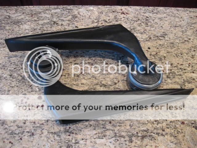
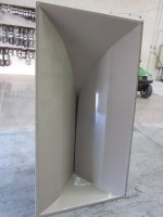
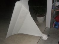
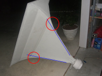
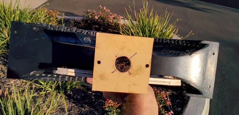
Here's some pics of the waveguide coming together.
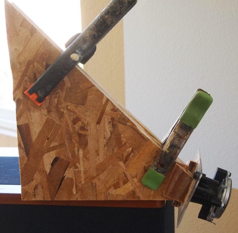
This one is close to finished. It's basically what I used for my measurements.
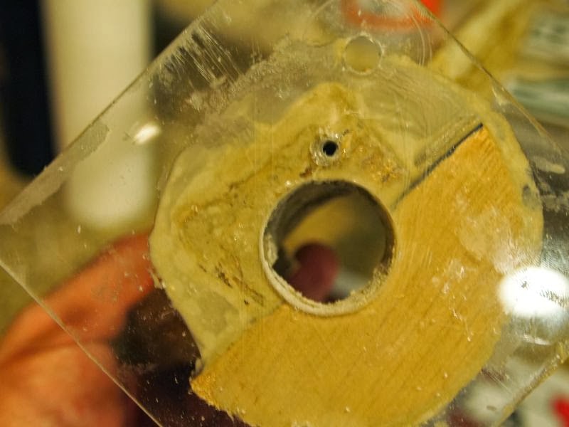
Better get that throat right. Plexiglass makes everything easier.
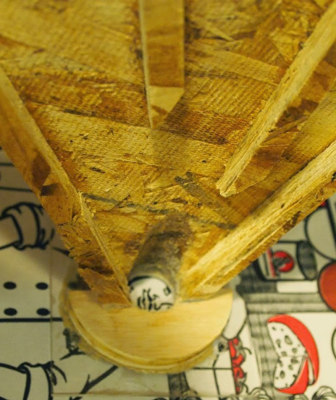
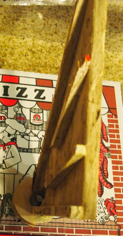

Inside of the waveguide. My usual crummy construction. Vanes are to stiffen the waveguide.
This week I was doing some sims, and it occurred to me that you *might* be able to get a similar radiation pattern using a waveguide with very wide horizontal bandwidth, but narrow vertical bandwidth.
So this thread is an attempt to find out.
For more information on why you might want to do this, check out the patents and writings of it's inventor, Manny LaCarruba(sp?)
In a nutshell, here's why you might want a speaker with this directivity pattern:
1) The narrow vertical directivity reduces reflections off of the floor and the ceiling
2) The very wide horizontal directivity reduces the need to be locked into the 'sweet spot.'
Here's some pics of the waveguide coming together.
This one is close to finished. It's basically what I used for my measurements.
Better get that throat right. Plexiglass makes everything easier.
Inside of the waveguide. My usual crummy construction. Vanes are to stiffen the waveguide.
Yes, that's exactly right.
Basically taking a Smith Horn, reducing the height, and flipping it on it's axis.
When a waveguide or horn isn't symmetrical, you get pattern flip. For instance, if you have a horn with a mouth that's 12" wide by 6" tall, the vertical directivity will beging to broaden about one octave before the horizontal. In this case, the vertical will broaden at about 2250hz, while the horizontal won't broaden until 1125hz. This is not A Good Thing; it will make the horn sound weird in the octave of 1125hz-2250hz, right in the middle of the midrange.
The obvious solution to pattern flip is to keep the horn symmetrical.
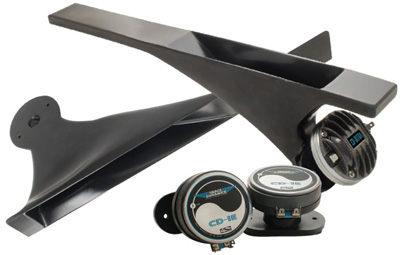
When Bruce Edgar helped Image Dynamics improve their horns, Bruce did something clever to combat 'pattern flip.' Instead of making the horn symmetrical, he made the vertical height so small, it drives up the pattern flip to a frequency that's very high.
If you look at the USD horn (first pic) and the ID horn (second pic) you can see that the second horn has a very small vertical height for most of it's path. This isn't accidental; it pushes pattern flip up to the last octave. So basically the ID horn has *wide* vertical directivity, and narrower horizontal directivity. Which is handy, since we're listening off-axis in both the vertical and horizontal axis.
My waveguide uses the same idea, but flips it 90 degrees.
Basically taking a Smith Horn, reducing the height, and flipping it on it's axis.
When a waveguide or horn isn't symmetrical, you get pattern flip. For instance, if you have a horn with a mouth that's 12" wide by 6" tall, the vertical directivity will beging to broaden about one octave before the horizontal. In this case, the vertical will broaden at about 2250hz, while the horizontal won't broaden until 1125hz. This is not A Good Thing; it will make the horn sound weird in the octave of 1125hz-2250hz, right in the middle of the midrange.
The obvious solution to pattern flip is to keep the horn symmetrical.
When Bruce Edgar helped Image Dynamics improve their horns, Bruce did something clever to combat 'pattern flip.' Instead of making the horn symmetrical, he made the vertical height so small, it drives up the pattern flip to a frequency that's very high.
If you look at the USD horn (first pic) and the ID horn (second pic) you can see that the second horn has a very small vertical height for most of it's path. This isn't accidental; it pushes pattern flip up to the last octave. So basically the ID horn has *wide* vertical directivity, and narrower horizontal directivity. Which is handy, since we're listening off-axis in both the vertical and horizontal axis.
My waveguide uses the same idea, but flips it 90 degrees.
Here's my waveguide, with a Celestion CDX1-1425
An externally hosted image should be here but it was not working when we last tested it.
Here's a Pyle PH714s. This is a $22 clone of some horn from the 70s, ElectroVoice I think. Not sure which one. Might be one of Don Keele's designs.

Here's the horizontal polars of my waveguide. Fairly hopeless. These include quite a bit of EQ to tame peaks and dips. I believe the peaks and dips are caused by the very low flare... Basically the mouth needs to be bigger. One of my inspirations for this horn was the Danley Paraline, which is about 1/4" in height. But the Danley expands in 360 degrees, while this only expands in 45 degrees. That means that the area of my horn mouth would be equivalent to a Paraline with a height of just 1/16th of an inch! That's what's causing all the peaks and dips IMHO.
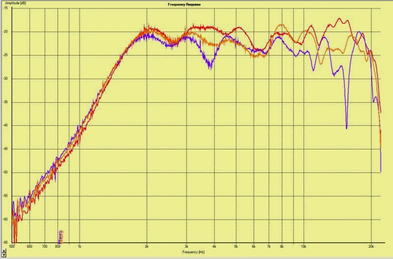
Here's the horizontal polars of the Pyle PH714s, with some EQ to flatten it out. The Pyle required less EQ and it's response is more consistent than the waveguide I built.
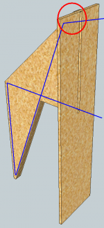
Nearly impossible to "see" in this drawing, cause long ago I erased
all the unnecessary drafting lines... But use your imagination...
Angled reflector at the top is NOT fully illuminated by the 20deg
wedge of the first expansion. And a ray trace of said reflection
misses by a few degrees conforming to the reflector as sidewall.
Therefore it acts like an expansion, just before the slot opening,
a round-over or whatever. I wanted to open a similar roundover
into the bottom lip of the slot. Not in this version of the drawing
unfortunately, so again use your imagination to pretend that cut.
This small expansion is insignificant compared to the 180 spread
when the wave leaves the slot, so there is going to be impedance
discontinuity for sure. Angled slightly upward in this drawing, not
straight ahead as it might at first glance appear. Your photograph
shows a similar slant to the opening. I was hoping that might help
smear around the damage, not to appear all as-if one big dip...
The OP of another thread that I drew this for didn't want it any
higher than 4ft tall. And I figure most peoples ears are sitting that
or standing higher. Therefore a slightly upwards slanted angle of
exit was part of the plan. A little disappointed your graph predicts
so many dips for me, with a similar exit strategy.
And we were looking at a Mantaray horn with crazy slanted exit,
and also slightly wider at the long end, I'm not entirely sure why...
Attachments
Last edited:
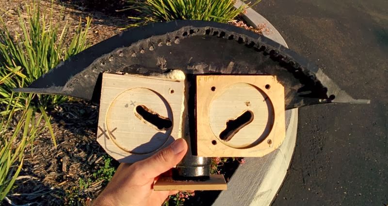
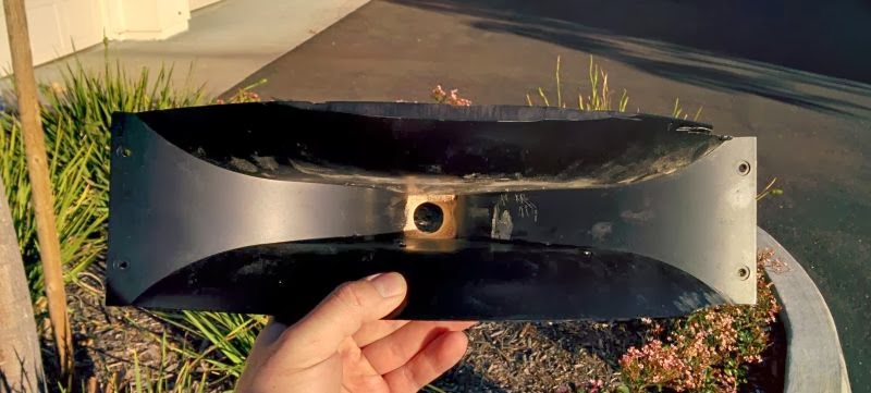
I believe these might be front and back pics of the Altec I was describing.
Since I ripped em' from different sights, they might not be of exactly the
same model. Anyways, note how the "long" end of the slot is also slightly
wider. What gives with that???
Might get rid some of those dips, if you were to slather on some bondo
and sand the throat area a little smoother, just sayin'...
Attachments
Last edited:


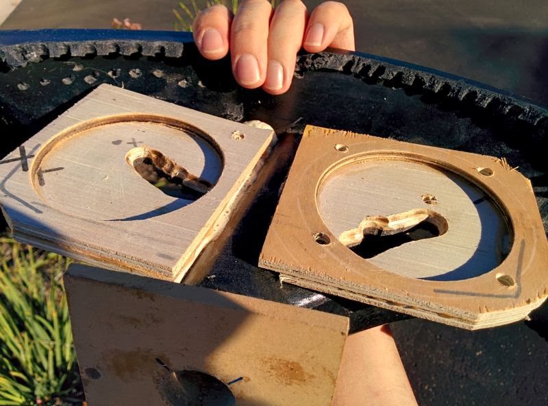
So again, look those Altec Mantaray pics.
I believe the pic on the right (side view)
might be sitting upside down with regard
to the pic on the left (front view).
Looking at the side view, we see a wedge
of straight sides, but a few inches before
the slot, we see a small vertical expansion.
Maybe a 2D "roundover". That sort of the
thing I was trying to achieve in post #6.
Though I was getting there (on the top side
only) by trick of the reflection angle. Little
or no actual roundover expansion to be cut...
If we look at the illuminated part of the top
edge as being part of the 20degree wedge
that reflects out the front slot. And the last
few inches of un-illuminated top edge as a
new wedge with wider angle of expansion.
Of course, I only gave treatment for the top
edge of the slot. Nothing similar was done
for my lower edge. If I'd noticed earlier those
expansions (just before the slot) in Altec's
example, I would have been more likely to
have wanted that feature for both ends too.
And some other weird bend at Altec's throat?
No idea what that was intended to accomplish.
Shape there is not making a lot of sense to me.
Attachments
Last edited:
Here's a video of the Pyle horn.
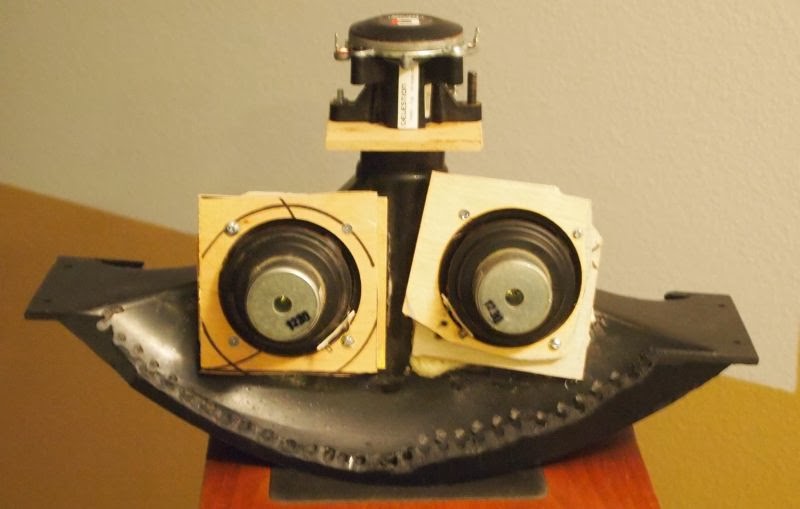
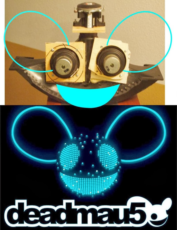
This is a Synergy horn, using the Pyle for the horn, the Celestion CDX1-1425 for the compression driver, the Dayton ND91 for midbass, mini DSP for crossover and EQ, an Ikea cube to simulate the effect of putting the horn under the dash of my car, and a blanket to turn the dipole into a cardioid.
Pyle Synergy Horn - YouTube
In particular, note how each instrument is distinct as the song builds to a climax at the two minute mark. While each member of the band is pounding away at their instruments, the sound does not get congested and the transients don't blur. That's a nice side effect of having the midrange and treble within a few inches of each other and loaded by the same horn.
Last edited:


Ken,And some other weird bend at Altec's throat?
No idea what that was intended to accomplish.
Shape there is not making a lot of sense to me.
The angular distortion in the pictures makes it difficult to determine what the horn actually looks like, but it appears to be designed for "long throw/short throw" use. EV and JBL also made similar units, with better smoothing than the Altec.
The horn appears upside down from it's typical intended use, which has the wider dispersion portion of the horn covering the near field, the more narrow dispersion upper portion covers more distant seating. The more narrow portion has higher sensitivity, which combats the inverse distance SPL fall off, if placed at the right height, sound level is more consistent front to back, and has a better direct to reflected ratio that a single horn with a single horizontal dispersion angle.
Normally the different horizontal dispersion needed for near and far is done with two separate horns and drivers, but combining two horns into one is more cost effective when the output level of two drivers is not required. That said, variable dispersion horns never seemed to catch on well in the contractor world, seems not many designers understood the unique properties.
I have searched using many different terms, seems the much smaller EV horns of this type are the only ones still in production, but are packaged in a cabinet with a 15".
Last edited:
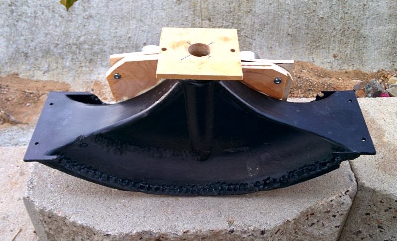
Here's some pics showing the evolution of this project.
Here's a pic and the horizontal polars of the first waveguide I made, which is basically a conical horn with zero degrees of horizontal directivity and 45 degrees of vertical directivity.
(Note that it's oriented *vertically*)
Here's the horizontal directivity of the Pyle PH714 when oriented vertically. Ideally I'd like to use a width of about 1" or less, which would basically make the horn omnidirectional up to 10khz or so. But this isn't easy to do; due to the small mouth the midrange gets lumpy. (As seen in the first set of measurements.)
So the Pyle might be as good as it gets, at least with this directivity pattern.
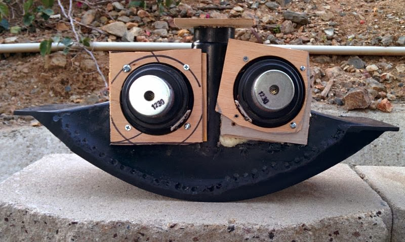
^^ Here's a pic of the Pyle, after I chopped it up and threw some mids on the horn, Synergy Horn style.
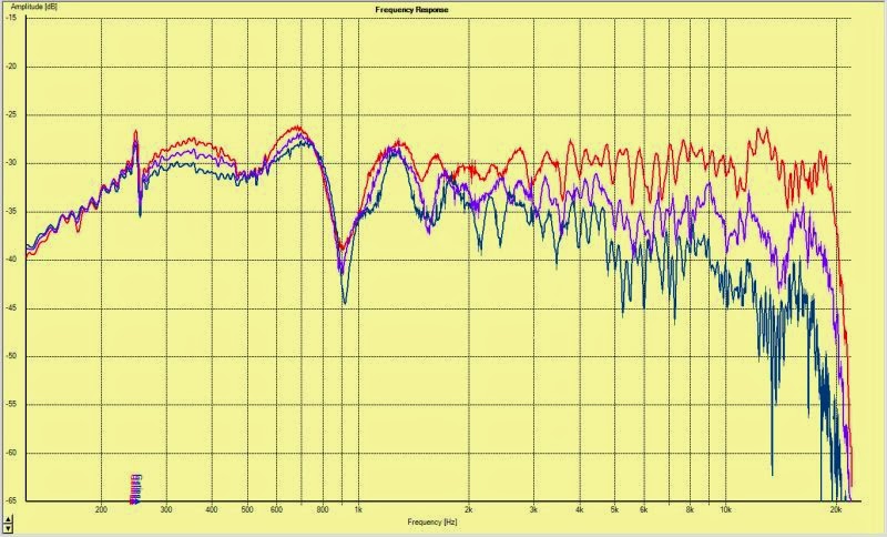
At this point, these are the best polars yet. Particularly the top two octaves, which are much smoother than the last two horns.

IMHO, the improvement in the Pyle is due to changes I made to the throat. In it's "stock" condition, the Pyle has a HUGE gap in the throat. We're talking almost half an inch. My second set of measurements had some clay in the throat, and even with the clay, the top octave was a little rough. For the last set of measurements here, I used a combination of Gorrilla Glue and sawdust to fill in the throat, and then I filed it down with a round file.

At this point, the biggest problem I'm dealing with is the phase at the crossover point. The tweeter is out-of-phase with the midrange at the xover point. The graph above shows the drivers in-phase (with a dip) and out-of-phase (with a smaller dip.)
I checked all my wiring, and it appears that everything is connected correctly. So either the terminals on the drivers are coded wrong, or (more likely) the dipole radiation is causing the dip in the midrange.
Basically, I think that there's enough energy coming off the *back* of the cones that it's creating a dip.
I tried using some digital delay on both the mids and the tweeter, and the dip didn't go away it just changed frequency, which would seem to confirm my hypothesis, that this is due to the dipole radiation.
Covering up the midranges with a blanket made quite an improvement, and that's why the video that I posted has them configured that way. I also did the measurements in a 13" cube, as I'm trying to replicate the effect of having the horn underneath the dash of a car.
My next steps will be to experiment with stuffing the back chamber to make it more of a cardioid and less of a dipole, and also stuffing the horn itself, a la Geddes
Here's a pic and the horizontal polars of the first waveguide I made, which is basically a conical horn with zero degrees of horizontal directivity and 45 degrees of vertical directivity.
(Note that it's oriented *vertically*)
An externally hosted image should be here but it was not working when we last tested it.
Here's the horizontal directivity of the Pyle PH714 when oriented vertically. Ideally I'd like to use a width of about 1" or less, which would basically make the horn omnidirectional up to 10khz or so. But this isn't easy to do; due to the small mouth the midrange gets lumpy. (As seen in the first set of measurements.)
So the Pyle might be as good as it gets, at least with this directivity pattern.
^^ Here's a pic of the Pyle, after I chopped it up and threw some mids on the horn, Synergy Horn style.
At this point, these are the best polars yet. Particularly the top two octaves, which are much smoother than the last two horns.
IMHO, the improvement in the Pyle is due to changes I made to the throat. In it's "stock" condition, the Pyle has a HUGE gap in the throat. We're talking almost half an inch. My second set of measurements had some clay in the throat, and even with the clay, the top octave was a little rough. For the last set of measurements here, I used a combination of Gorrilla Glue and sawdust to fill in the throat, and then I filed it down with a round file.
At this point, the biggest problem I'm dealing with is the phase at the crossover point. The tweeter is out-of-phase with the midrange at the xover point. The graph above shows the drivers in-phase (with a dip) and out-of-phase (with a smaller dip.)
I checked all my wiring, and it appears that everything is connected correctly. So either the terminals on the drivers are coded wrong, or (more likely) the dipole radiation is causing the dip in the midrange.
Basically, I think that there's enough energy coming off the *back* of the cones that it's creating a dip.
I tried using some digital delay on both the mids and the tweeter, and the dip didn't go away it just changed frequency, which would seem to confirm my hypothesis, that this is due to the dipole radiation.
Covering up the midranges with a blanket made quite an improvement, and that's why the video that I posted has them configured that way. I also did the measurements in a 13" cube, as I'm trying to replicate the effect of having the horn underneath the dash of a car.
My next steps will be to experiment with stuffing the back chamber to make it more of a cardioid and less of a dipole, and also stuffing the horn itself, a la Geddes
It looks pretty happy too 
So the Pyle might be as good as it gets, at least with this directivity pattern.
^^ Here's a pic of the Pyle, after I chopped it up and threw some mids on the horn, Synergy Horn style.
At this point, these are the best polars yet. Particularly the top two octaves, which are much smoother than the last two horns.
And some other weird bend at Altec's throat?
No idea what that was intended to accomplish.
Shape there is not making a lot of sense to me.
http://www.lansingheritage.org/images/altec/catalogs/1993-pro/1993-24.JPG
http://www.lansingheritage.org/images/altec/catalogs/1993-pro/1993-25.JPG
GM
Here's some more pics of the horn coming together.

Here's the floor of my car. Yes I was too lazy to vacuum it.
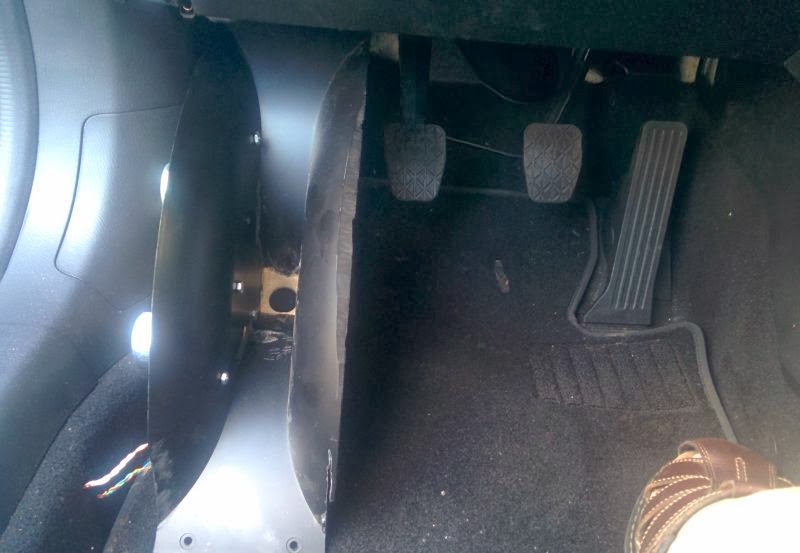
Here's the floor with the horn in place. While the horn extends fairly deep into the cabin, the source of the sound is basically in the kick panel, which is known to image very well in cars. (The horn mouth extends 30cm towards the driver, but the sound actually radiates from the throat, and the perception of sound location will most be the throat, though part of that will be frequency dependent. (The higher in frequency, the further back the sound will appear to emanate from.)

Here's a side shot. You can see that the main thing keeping me from pushing the horn back further is the motor of the midbasses. It would be possible to push it back further if I moved the entire horn to the right, but then it will get in the way of the clutch pedal.

Here's how a conventional HLCD looks in a car with a clutch; it definitely takes a little getting used to having speakers so close to the pedals. I actually came close to rear ending someone once when I tried to hit the brake and wound up knocking my horns loose, which then fell down, blocking the very pedal I was trying to hit in the first place. Had to pull the emergency brake to slow the car down :O
Here's the floor of my car. Yes I was too lazy to vacuum it.
Here's the floor with the horn in place. While the horn extends fairly deep into the cabin, the source of the sound is basically in the kick panel, which is known to image very well in cars. (The horn mouth extends 30cm towards the driver, but the sound actually radiates from the throat, and the perception of sound location will most be the throat, though part of that will be frequency dependent. (The higher in frequency, the further back the sound will appear to emanate from.)
Here's a side shot. You can see that the main thing keeping me from pushing the horn back further is the motor of the midbasses. It would be possible to push it back further if I moved the entire horn to the right, but then it will get in the way of the clutch pedal.
Here's how a conventional HLCD looks in a car with a clutch; it definitely takes a little getting used to having speakers so close to the pedals. I actually came close to rear ending someone once when I tried to hit the brake and wound up knocking my horns loose, which then fell down, blocking the very pedal I was trying to hit in the first place. Had to pull the emergency brake to slow the car down :O
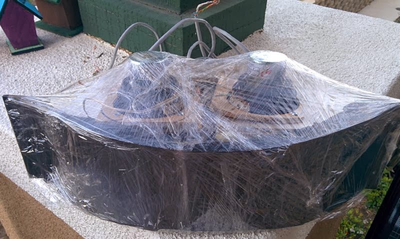
With the back of the cone about 25cm away from the front of the cone, we should see the low frequencies start to rolloff in the octave from 170-340hz. (I'm too lazy to fire up The Edge to see the exact frequency, and besides, a horn loaded dipole will behave differently than a flat baffle)
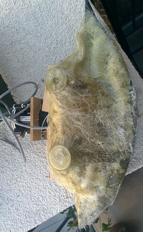
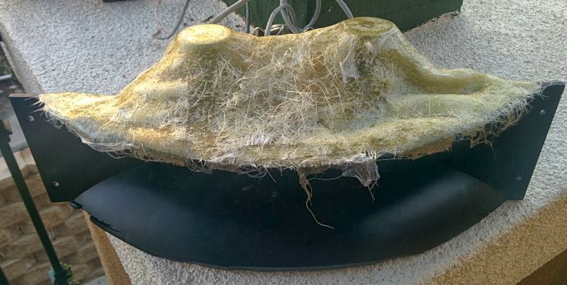
I made a fiberglass cover to increase output at low frequency. Basically just wrapped the entire speaker in saran wrap, glassed it, put on more saran wrap to compress the fibers, then let it cure.
- Status
- This old topic is closed. If you want to reopen this topic, contact a moderator using the "Report Post" button.
- Home
- Loudspeakers
- Multi-Way
- Edge of No Control