Respected friends,
I started this thread here as per the suggestion of two experienced members.
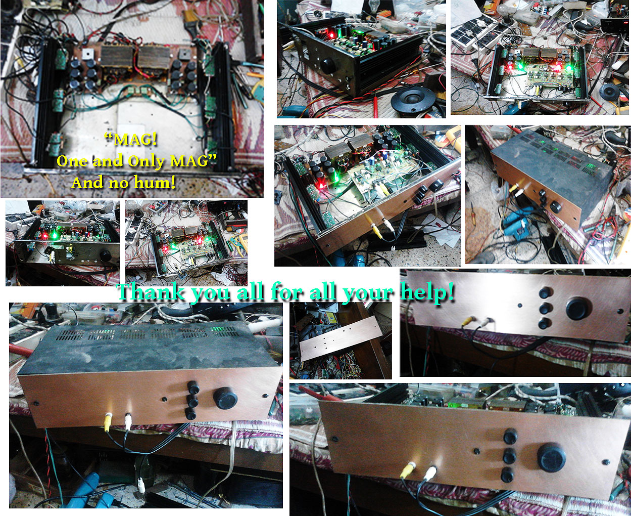
I just finished a 3 way Active LM3886 Amplifier system with the kind help of all the great people in the chip amp thread here.
http://www.diyaudio.com/forums/atta...-gainclone-active-amplifier-lm3886-update.jpg
I am getting a very good and impressive dynamic sound with deep bass from a pair of my earlier not so "grammatically" built 3 way Floor Stander speakers even with non standard cheap drivers.
But I have no idea whether the sound is fully optimized or not or if it can be be made better with a better enclosure.
I want to build the enclosure as small as possible yet preserving the quality due to the space constraint in my room with your help.
For that, I need a plan to suit my drivers.
The size of the woofer is 6.5 inches.
The midrange is 4 inches and the tweeter is 2 inches.
Unfortunately no specific data is available about the unbranded drivers.
I am using an Active 3 way Xover to drive 6 set of LM3886 amps.
2 amps for woofers, 2 for midrange drivers and 2 for tweeters.
Room Size is 10 ft X 12 ft approximately.
Math is not my piece of cake.
My only skill is that I can make PCBs with toner transfer method and solder them satisfactorily.
Hence I need your handholding sincerely with a plan for a 3 way active speaker enclosure design for my newly built system.
Kindly help me out.
Thank you all.
I started this thread here as per the suggestion of two experienced members.
I just finished a 3 way Active LM3886 Amplifier system with the kind help of all the great people in the chip amp thread here.
http://www.diyaudio.com/forums/atta...-gainclone-active-amplifier-lm3886-update.jpg
I am getting a very good and impressive dynamic sound with deep bass from a pair of my earlier not so "grammatically" built 3 way Floor Stander speakers even with non standard cheap drivers.
But I have no idea whether the sound is fully optimized or not or if it can be be made better with a better enclosure.
I want to build the enclosure as small as possible yet preserving the quality due to the space constraint in my room with your help.
For that, I need a plan to suit my drivers.
The size of the woofer is 6.5 inches.
The midrange is 4 inches and the tweeter is 2 inches.
Unfortunately no specific data is available about the unbranded drivers.
I am using an Active 3 way Xover to drive 6 set of LM3886 amps.
2 amps for woofers, 2 for midrange drivers and 2 for tweeters.
Room Size is 10 ft X 12 ft approximately.
Math is not my piece of cake.
My only skill is that I can make PCBs with toner transfer method and solder them satisfactorily.
Hence I need your handholding sincerely with a plan for a 3 way active speaker enclosure design for my newly built system.
Kindly help me out.
Thank you all.
No plan can be suggested without knowledge of said drivers specifications. What your tastes are in music, decor, etc.
More detailed information is required to proceed
Thank you for your reply.
I tried to obtain the driver specification on net, but I simply failed.
Will it be helpful if I post some photos of my drivers?
I like listen to all kind of music e.g. Jazz, Rock, Pop, Oriental, almost everything depending on the mood.
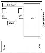
Regarding décor, I have attached a picture.
Attachments
You can always pick from known designs.
Statement monitors designed by Jim Holte look like it meets your requirements. just order the speakers a la carte since you don't need a passive x-over.
Thank you for your reply.
I have no online purchase facility yet.
Could you kindly post some links to free plans or known designs?
I posted the picture of the arrangement of my room in the previous post.
I apologize as I didn't read your initial post correctly. i assumed that you were looking for speakers that fit that description as opposed to already having those drivers. Pics of the drivers will help as that is currently the only piece of info you have to identify them. Hopefully they are recognizable from a known company and can be ID'd. Unfortunately the size of the speaker will heavily rely on the characteristics of the woofer.
Thank you for your reply.
I have no online purchase facility yet.
Could you kindly post some links to free plans or known designs?
I posted the picture of the arrangement of my room in the previous post.
My suggestion would be to concentrate on the woofer first, as most of the space will be taken up by the enclosure for the woofer.
Stick with a sealed enclosure for the woofer, as some misalignment with a sealed system is not too important.
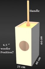
A 6.5" woofer probably won't need an enclosure with more than 64 liters internal volume. So you should make a test box with that internal volume. That works out to 25 cm by 40 cm by 64 cm on the inside of the box. Make the box so that you have some way to decrease the internal volume in steps.
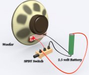
Make a damping tester from a 1.5V battery and a SPDT switch. The pole of the switch is connected to the (+) terminal of the woofer. A first throw of the switch connects to (+) of the battery. The second throw of the switch connects to (-) of the battery and woofer.
For the 64 liter box, probably you will hear a click each time you make and break the connection of the battery to the woofer. What you would want to do is decrease the size of the box as much as possible while still getting a click-sound on make and break of the switch. When you hear a thud or a bong on make or break, the size of the box has been made too small.
By listening to music, check that bass response is adequate where the box size is that which was selected by using the damping tester.
Stick with a sealed enclosure for the woofer, as some misalignment with a sealed system is not too important.
A 6.5" woofer probably won't need an enclosure with more than 64 liters internal volume. So you should make a test box with that internal volume. That works out to 25 cm by 40 cm by 64 cm on the inside of the box. Make the box so that you have some way to decrease the internal volume in steps.
Make a damping tester from a 1.5V battery and a SPDT switch. The pole of the switch is connected to the (+) terminal of the woofer. A first throw of the switch connects to (+) of the battery. The second throw of the switch connects to (-) of the battery and woofer.
For the 64 liter box, probably you will hear a click each time you make and break the connection of the battery to the woofer. What you would want to do is decrease the size of the box as much as possible while still getting a click-sound on make and break of the switch. When you hear a thud or a bong on make or break, the size of the box has been made too small.
By listening to music, check that bass response is adequate where the box size is that which was selected by using the damping tester.
......... Pics of the drivers will help as that is currently the only piece of info you have to identify them. Hopefully they are recognizable from a known company and can be ID'd. ........
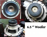
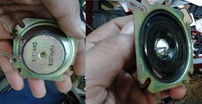
Thank you so much for the reply.
Here are some photos of the drivers. Kindly have a look, all.
")
For the midrange section, I am using an old Philips 4'' full range driver with its enclosure.
Attachments

Last edited:
My suggestion would be to concentrate on the woofer first, as most of the space will be taken up by the enclosure for the woofer.
Stick with a sealed enclosure for the woofer, as some misalignment with a sealed system is not too important.
A 6.5" woofer probably won't need an enclosure with more than 64 liters internal volume. So you should make a test box with that internal volume. That works out to 25 cm by 40 cm by 64 cm on the inside of the box. Make the box so that you have some way to decrease the internal volume in steps.
Thank you so much.
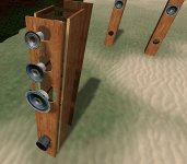
I am a bit lost with the placement of the woofer whole in the enclosure.
Kindly have a look at the 3d drawing in the attachment.
Make a damping tester from a 1.5V battery and a SPDT switch. ...............
..................
I tried to make that in 3d, kindly correct me if I am wrong.
Attachments
Measure what you have and this will help with those unknown specs.
Measuring Thiele / Small Loudspeaker Parameters
ARTA (LIMP) and Room Equalization Wizard (REW) can measure FS, frequency response and room acoustics. Get yourself a a calibration microphone, like a UMIK-1 from MiniDSP, something that Parts Express carries several or if your friends already have one to make these measurements. These can be made if you are handy with electronics too. Many are available for little cost, soaring to WOW that's pricy (but deadly accurate) types.
Now I have a pair of DIY floor standers. I made them without any "grammar".Measure what you have and this will help with those unknown specs.
Measuring Thiele / Small Loudspeaker Parameters
I will read the link minutely.
ARTA (LIMP) and Room Equalization Wizard (REW) can measure FS, frequency response and room acoustics.
I will download, install and post the result with snapshots here.
Get yourself a a calibration microphone, ...........These can be made if you are handy with electronics too. .......
I want to make it. Could you kindly help me?
Thanks a lot.
Attachments
Last edited:
A DIY calibration microphone can be fairly accurate without a calibration file within reason. For one to be "calibrated" it would need to be sent out and tested. There are those here on these forums that offer this service. If building your own and want known accuracy (and we all do ultimately) this would add to the cost. Many of the cheaper ones like those linked above include the calibration file and use USB vs. analog preamp w/ phantom power supply.
Here is a quick search, Google is your friend.
You'll find many of these links will lead you back to these forums
Here is a quick search, Google is your friend.
You'll find many of these links will lead you back to these forums
That tall narrow enclosure is more of a transmission line due to it's shape and the software normally used to model bass reflex type designs won't work. Either subdividing the lower section (or upper which would solve the open back fullrange issue) so as to be shorter on the interior (if woofer allows it) or a shorter one that is a bit wider and deeper up on a stand.
I cannot say at this juncture if the woofer would work or not in a TL or if that's what you would want.
BTW your exploded view is a MLTL (mass loaded transmission line) speaker and as such is improperly configured (but quite close
I cannot say at this juncture if the woofer would work or not in a TL or if that's what you would want.
BTW your exploded view is a MLTL (mass loaded transmission line) speaker and as such is improperly configured (but quite close
Last edited:
.................
Here is a quick search, Google is your friend.
You'll find many of these links will lead you back to these forums
Thank you Sir, I will read the links and ask when I get stuck.
That tall narrow enclosure is more of a transmission line due to it's shape and the software normally used to model bass reflex type designs won't work. Either subdividing the lower section (or upper which would solve the open back fullrange issue) so as to be shorter on the interior (if woofer allows it) or a shorter one that is a bit wider and deeper up on a stand.
I cannot say at this juncture if the woofer would work or not in a TL or if that's what you would want.
BTW your exploded view is a MLTL (mass loaded transmission line) speaker and as such is improperly configured (but quite close
I just made those floor standers with a blind guess with some half inch plywood board. These are not open back type. These are sealed but there is a 4 inches bass reflex port at the bottom.
To be honest I have no technical back ground. So a Lot to learn. I have no idea what a TL or MLTL does in comparison to the normal speaker enclosure
.
Kindly forgive my ignorance and forthcoming (perhaps) repetitive silly questions.
I do hope to tune/fine tune or redesign it with all of your kind help.
Thank you sir.Nice looking exploded view!
Not sure if its intentional but I noticed the brace under the midrange is open and there doesn't seem to be any implementation of sealing off the 4" midrange from the 6.5" woofer. Just making sure if that was accounted for
You are right. I didn't know they should be separated.
I feel fortunate that I'm in the privileged company of the experts now.
The amp I made, with the kind help of respected chip amp experts, is just brilliant.
So I want to do a justice to it by giving it two suitable companions.
So kindly feel free to advice. I need to learn a lot from you all.
I just made those floor standers with a blind guess with some half inch plywood board. These are not open back type. These are sealed but there is a 4 inches bass reflex port at the bottom.
Open baffle would be correct and is a whole different critter from your pictures.
To be honest I have no technical back ground.
You already have the best gift one can have, Curiosity and a willingness to learn
YesSo a Lot to learn.
I have no idea what a TL or MLTL does in comparison to the normal speaker enclosure.
Sound is different. Most say more dynamic and lively. The difference is in how the system works. With Thiel/Small parameters we can make a bass reflex enclosure with ease, but how this loads the woofer is different. With a BR the volume of the enclosure is X and the system is then tuned with a port. A transmission line works based on the ¼ wavelength frequency detirmined byvthe length of the enclosure and the port is tuned to the resonance of the woofer. Let me state it this way, Length of enclosure tunes the system, not the port. This design allow maximal dampening of the woofer at resonance and a smoother low end roll off are it's advantages.
Thank you so much.
I am a bit lost with the placement of the woofer whole in the enclosure.
Kindly have a look at the 3d drawing in the attachment.
I tried to make that in 3d, kindly correct me if I am wrong.
The drawings are exactly what I suggested. The hole for the woofer might be better placed more towards one end of the test box, maybe at one third of the total height of box, so you could make the test volume one-half of the maximum.
The method I'm suggesting would be good if you wanted to quickly assemble some speakers. Certainly measuring the specifications of the woofer and then designing the speaker according to those measurements is the superior way to go. But the process of obtaining the specifications of the woofer by your own measurement will be time consuming.
Your drawings are excellent! It looks like working with a computer is a piece of cake for you.
Regards,
Pete
Would suggest if you follow cT's advise to place the port on the backside (so you won't hear port resonances) and to place it no higher than 7.5 cm from the bottom. Port length will be short, for a 7.5cm diameter port length would be around ~10-15cm long. Start long and trim to adjust. Lite amount of dampening material in the upper third of enclosure.
Measuring driver parameters are not that time consuming, far less than repeatedly guessing what needs to change.
Measuring driver parameters are not that time consuming, far less than repeatedly guessing what needs to change.
Would suggest if you follow cT's advise to place the port on the backside (so you won't hear port resonances) and to place it no higher than 7.5 cm from the bottom. Port length will be short, for a 7.5cm diameter port length would be around ~10-15cm long. Start long and trim to adjust. Lite amount of dampening material in the upper third of enclosure.
Measuring driver parameters are not that time consuming, far less than repeatedly guessing what needs to change.
My suggestion was to put the woofer in a sealed system. I think that designing a ported system by trial and error without knowing any of the parameters of the woofer would be really difficult (in achieving good reproduction).
With the technique that I proposed, all that you do is decrease the volume until Q of the woofer starts to get to be too high, evidenced by hearing a "thud" or a "plop". When you find out what the threshold volume is, then you are done with the alignment. To my mind, this isn't too bad of a technique when designing a closed box for a woofer that you know virtually nothing about.
If you frequently do measure parameters of drivers and already know how to go about it, then I agree, that isn't too much trouble. That isn't the OP's situation. If that is something that he is willing to learn to do and may use again in the future, then maybe that would be a good route for him to take.
Depending on the individual, building the test box might or might not be more time consuming than measuring the Thiele/ Small parameters. I don't know, is it possible to measure Vas with a computer program? If not, then again you need to make either a test box or add mass to the driver while taking measurements.
Regards,
Pete
- Status
- This old topic is closed. If you want to reopen this topic, contact a moderator using the "Report Post" button.
- Home
- Loudspeakers
- Multi-Way
- Need Help with The Smallest 3 way Speaker Plan for LM3886 Triamping