By that I meant single channel + loopback, not dual FFTs. Sorry if my terminology was off.I did not know that REW had dual ch… I know there was some chatter about it on the AVNirvana pages , but I never saw anything happen with it..
Have you tried Open Sound Meter?Smaart and FIR designer work together.
They have each other‘s software embedded so they talk to each other it’s super cool but I am a full-blown diehard RePhase fan. I’m super loyal once I get something that works and I absolutely love multi mic averages in smaart. It truly is the best way. I can get good phase to 20k (not kidding)…
The problem with REW is you can’t average the phase. So a single mic is only good to like 1k ish … 2k if your good…
I basically align all my speakers with a single static mic time using the tweeter as the mic time…. Then align with dsp delay all drivers to impulse peak single mic
Then I bring out the big guns and do a mic array around the head space and get a multi mic average. The phase is pristine the way smaart removes the time of flight… it’s perfect. The dual ch is a must for FIRs IMO.
I did not know that REW had dual ch… I know there was some chatter about it on the AVNirvana pages , but I never saw anything happen with it..
I have the pro version of REW and it works… it’s nothing like smaart.
I’ve heard of people getting pirate versions of V8…. I don’t know if you like to wear a patch over your eye and have a parrot on your shoulder…food for thought.
But it sounds like what you’re doing is pretty cool. And if you were getting results that you like then, there’s no arguing with results.
Kind of new to this software but am I going about it right? I created some LR2 linear phase filters and loaded them up into EQ APO for a 3 way crossover. The phase measures very linear and the response is great, but it sounds a but, odd? Really hard to put my finger on it. Not even sure where to start on tracking down why.
Hi waffle!
Don't forget to remove inverted polarity on the mids.
I think the biggest difference in my 3 way conversion was that the faint "whistling noise" disappears (which I think I hear when the phase is rotated in normal LR 12 db). Unfortunately, my machine has a 6sec preset load time, so not quite optimal for A-B testing.
One easy test would be to try the exact same crossover slopes, but this time without the linear phase. Do remember to invert polarity on one of the two drivers in this case.
Does it sound different? More pleasing?
Do note that applying a named crossover like LR2 isn't a guarantee for the right slope you would need. Eventually it isn't the (named) crossover slope that's applied that makes it work, it's the acoustic output that should follow that LR2 slope. Together with the right timing, with LR2 and no phase linearity that means inversion of one of the drivers, it would sum favorably at the crossover point. Without one inverted source it should show a dip at the crossover frequency. Instead of the inverted driver one could use delay. Either digitally or an offset driver.
I'm trying to create a linear phase filter with rePhase, then export the coefficients and plot them in another piece of software.
Attachment #1 shows the filter in rePhase, with linear phase.
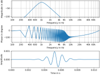
Attachment #2 shows the the outcome of plotting the coefficients using a Python audio processing library. This time, see how the phase is all over the place.
I raised the issue with the Python library here, and the decision is that the library is correctly plotting the inputs it was given.
So I'm not sure where the discrepancy lies. Surely rePhase IS correctly producing a filter with linear phase because otherwise everyone would be seeing incorrect measurements in REW... Anyone have any thoughts?
Attachment #1 shows the filter in rePhase, with linear phase.
Attachment #2 shows the the outcome of plotting the coefficients using a Python audio processing library. This time, see how the phase is all over the place.
I raised the issue with the Python library here, and the decision is that the library is correctly plotting the inputs it was given.
So I'm not sure where the discrepancy lies. Surely rePhase IS correctly producing a filter with linear phase because otherwise everyone would be seeing incorrect measurements in REW... Anyone have any thoughts?
Attachments
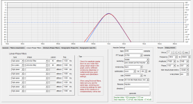
The filter you are making does not match the target that closely. If you increase the number of taps or reduce the sampling frequency the red and blue lines will overlay more closely.
The impulse is not symmetric which suggests it is not linear phase.
Is the fixed delay to make the filter causal being removed in the plotting of the phase?
Leaving the time delay in makes phase plot like that.
The impulse is not symmetric which suggests it is not linear phase.
Is the fixed delay to make the filter causal being removed in the plotting of the phase?
Leaving the time delay in makes phase plot like that.
I hadn't accounted for the delay originally, but the results are still similarly "wrong" with the following code in my script:
Setting the impulse delay to 0 or 1024 (the delay given by rePhase) both comes out wrong, still.import matplotlib.pyplot as plt
import pyfar as pf
import pyfar.classes.filter as pff
import pyfar.plot as pfp
# create an impulse against which to apply the filter
i = pf.signals.impulse(n_samples=4096, sampling_rate=192000, delay=1024)
# create an FIR filter object
fir_filter = pff.FilterFIR(coeffs, sampling_rate=192000)
# process the impulse signal against the FIR filter
filtered_signal = fir_filter.process(i)
# <-- code to plot the filtered signal -->
Without an image it is hard to see what changed, but probably both are correct for the filter you made, just not what you expected.
Maybe try a simpler filter like a 3K high pass LR24 to start with to work out any kinks with the settings in the program.
REW can plot rephase filters with no problem when the correct impulse start is chosen, and when the rephase settings are chosen properly the expected result is seen. Check the impulse to see if it is symmetric.
- Home
- Design & Build
- Software Tools
- rePhase, a loudspeaker phase linearization, EQ and FIR filtering tool