Hi dear,
I want to mod my kef iq3 speakers (capacitor´s, wires... )
anyone has the schematic of KEF IQ3 speakers ?
I will apreciate,
best regards
I want to mod my kef iq3 speakers (capacitor´s, wires... )
anyone has the schematic of KEF IQ3 speakers ?
I will apreciate,
best regards
Today I modify my pair of IQ3 witch I bought last week.
I change all the capacitors with Bennic and Visaton the resistor with Mundorf, and DIY coil.
Also the cable was changed with Real Cable.
Bass C 16uF/250v Bennic, R 6.8ohm, L 1.1mH
Tweeter C1 15uF/250v Visaton. C2 5.6uF/250v Bennic, R 1.2ohm L 0.125mH
The sound for this speaker after the modification in unbelievable, sound is more accurate more clean.
circuit board
gabriel and hcbonfim, and anyone else ...
how did you get the crossover circuit board out of the cabinet ?
In my iQ3 the board is very tightly held by plastic, or nylon, studs and will not come off over them.
I do not want to break the circuit board.
Perhaps I will have to cut the tops off the retaining studs,
or break the corners off the circuit board.
Any suggestions from anyone who has done this please ?
Hi,
do the plastic studs have a "core" in the middle.
This pushes out to release the tangs on the other side to allow dismantling.
Can the sides of the protruding stud be squeezed in to release the PCB?
I have some Ci 130QS.
Are these the same drivers as in the IQ3?
do the plastic studs have a "core" in the middle.
This pushes out to release the tangs on the other side to allow dismantling.
Can the sides of the protruding stud be squeezed in to release the PCB?
I have some Ci 130QS.
Are these the same drivers as in the IQ3?
seems not
Hi Andrew,
I tried squeezing the sides of the studs, but they do not push in.
I think I tried pressing the tops, and I didn't notice a push-in function in the tops.
It looked like the board is simply pushed on over non-retractable retaining studs - the cheapest possible type.
My guess is that KEF do not intend these to be removed for Servicing even,
unless their technicians have a special tool to remove the boards from the studs ...
Its all silly, because the capacitors are all electrolytics, thus limited service life as well as slightly fuzzy sound,
BUT the drivers seem to be very good and worth a better quality components' crossover !
The drivers are co-axial - a metal dome tweeter mounted in the centre of a metal coated, plastic cone mid-bass driver.
The iQ3 and the new iQ30 have 165mm -{6 1/2"}- diameter drivers.
iQ1 and iQ10 have 130mm -{5 1/4"}- diameter co-axial drivers.
I have not seen Ci 130QS, nor any in the Ci series.
The basic C series drivers are not co-axials, but are separately placed tweeter and mid-bass drivers.
It looks like the Ci 130Q is an equivalent to the iQ1 & iQ10
The Ci160Q seems like the equivalent to iQ3.
I would expect the q & Vas of the bass/mid to be quite different, but the mid range and treble should be very similar.
The Ci160Q seems like the equivalent to iQ3.
I would expect the q & Vas of the bass/mid to be quite different, but the mid range and treble should be very similar.
Hi Alan
If you want to remove the crossover you must remove also the speakers terminal in the rear, with a lantern you will se the crossover and the all four plastic supports.
You will figure how to take it out. If not you can cut them. Use screw to fix the new crossover.
Forget about the Kef crossover, after a lot of A/B tests with a few speakers like Triangle Genese Trio and Jamo D830 I decide to replace the stock crossover with an older design from a Grundig Super HI-FI box 450 This has a crossover frequency at 1.5 kHz. I will try to put later the schematic diagram of the crossover. If any body wants to see the differences between the original crossover and the Grundig can build one and make some test. I use these speakers with an Onkyo A 8870.
Uni-Q drivers
Hi Andrew,
I found I do have a small brochure about the Ci series.
The pictures are small and the Dimensions are stated for the drivers in their mountings only, thus I am not sure what the actual drivers' diameters are.
On the back of my 6.5" driver's chassis is a KEF sticker with the Part Number :- SP1535 .
SP**** for part numbers has been used by KEF for many, many years.
The drivers in the iQ10 and iQ30 look to have the same cones and domes as their predecessors in iQ1 and iQ3, but there is now also what KEF call a Tangerine Waveguide - metal pieces protruding from the tweeter's flange - in the 10, 30, and all the new iQ*0 series.
This disperses the upper treble frequencies around the forward response area more widely than occurred with the previous iQ* series, BUT, and I have listened to both iQ3 and iQ30, the actual spectral content is different from different listening axis, and for some musical instruments I like the upper treble sounds untidy - so I am staying with my iQ3, but some listeners may prefer the new series - it spreads the sounds of cymbals well, but for pitch-specific harmonics, such as from violins, the Timbre changes too much for my liking when I move my head sideways even a little when listening.
iQ*0 series have apparently better capacitors in their crossovers AND the cross point has been moved down in frequency a little, thus I want to try that because a small amount of the inevitable cone breakup is audible, and crossing lower will reduce that audibility.
It is NOT highly intrusive breakup - unlike the large amount of midrange resonances that come out via the port !
With the port blocked sounds much better to me, and the bass is better pitch defined then also.
Q and Vas, etc will depend on whether same magnet size and type is used for the Ci series drivers as for iQ series, and perhaps they are.
Hopefully you can find out via the Part Number I noted above, as the 130mm drivers will have specific SP**** numbers.
iQ30 driver will have a different SP**** to iQ3's because the tangerine waveguide is part of the driver.
iQ3 driver does NOT look like the driver pictured in the new Ci160.2QS,
BUT, it does look like the driver in new Ci130.2QS, and that does not have the tangerine waveguide !
Crossover
Hi Gabriel,
Thankyou for you comments about how to access the in-cabinet crossover.
I am very interested to see a schematic for a better sounding crossover, if you are able to Post it or describe where it can be found.
See my new Post, above, for more of my thinking about the iQ3 driver and crossover hopes.
Hi Alan
I will draw the schematic. I will tell you also the value for coils and capacitors.
For the woofer a 22uF and a resistor 2.7ohmi the value for coil is 1.45mH and for tweeter a capacitor 8.2uf and a 0.43mH coil.
The crossover is second order.
first diagram is the woofer
I will draw the schematic. I will tell you also the value for coils and capacitors.
For the woofer a 22uF and a resistor 2.7ohmi the value for coil is 1.45mH and for tweeter a capacitor 8.2uf and a 0.43mH coil.
The crossover is second order.
first diagram is the woofer
Attachments
crossover frequency
Hi Gabriel,
1.5kHz frequency will be too low to cross to the tweeter in the iQ3, as it will be too close to the tweeter's Fs and thus there will be audible distortion when driven to high SPL level.
BUT, with the 8.2uF and .43mH in the Schematic you drew, those will resonate at about 2.65kHz and that will be suitable for the tweeter in the iQ3 !
Also, 8.2uF and .43mH is very close to Linkwitz-Riley LR2 alignment for approximately 3.6ohm Impedance, and the iQ3 tweeter will be approximately that Impedance around its 2.65kHz region, thus I think your crossover will work OK for the tweeter.
For the woofer I do not know, because the 22uF + 2.7ohm is part Zobel and part Filter, but as you have tried it and like it, I have no doubt that it works OK.
For LR2 crossover, one usually connects the tweeter in opposite Polarity -{some say "opposite Phase"}- to the woofer.
Is this how you have connected it for your listening ?
Forget about the Kef crossover, after a lot of A/B tests with a few speakers like Triangle Genese Trio and Jamo D830 I decide to replace the stock crossover with an older design from a Grundig Super HI-FI box 450 This has a crossover frequency at 1.5 kHz. I will try to put later the schematic diagram of the crossover.
.
Hi Gabriel,
1.5kHz frequency will be too low to cross to the tweeter in the iQ3, as it will be too close to the tweeter's Fs and thus there will be audible distortion when driven to high SPL level.
BUT, with the 8.2uF and .43mH in the Schematic you drew, those will resonate at about 2.65kHz and that will be suitable for the tweeter in the iQ3 !
Also, 8.2uF and .43mH is very close to Linkwitz-Riley LR2 alignment for approximately 3.6ohm Impedance, and the iQ3 tweeter will be approximately that Impedance around its 2.65kHz region, thus I think your crossover will work OK for the tweeter.
For the woofer I do not know, because the 22uF + 2.7ohm is part Zobel and part Filter, but as you have tried it and like it, I have no doubt that it works OK.
For LR2 crossover, one usually connects the tweeter in opposite Polarity -{some say "opposite Phase"}- to the woofer.
Is this how you have connected it for your listening ?
Last edited:
Hmmm. Have a pair of older Q1's. Not bad, just overly tame. Maybe a peek at the crossover is in order.
look at its driver connections
Hi tvrgeek,
the Q1 does not have the metal coated plastic diaphragm that iQ3 and iQ30 have, and I think Q1 has a plastic diaphragm that is thicker than the more recent models - if so, it will sound a bit slower as result of the Inertia of the heavier cone.
Is the cone in yours a simple plastic, or has it a coating of something ?
The cone in iQ3 is very thin and light weight, thus can move fast.
The dual layer of metal plus plastic provides both stiffness and damping of resonance, and it sounds as if only a small resonance in the upper midrange - past the crossover point.
Look also at the drivers' connections to the crossover.
Are both drivers connected in the same Polarity -{phase}- or is one connected in the opposite Polarity to the other ?
Opposite polarity connected drivers always produce a loudspeaker which sounds a bit "tame" compared to same or similar drivers connected in like-polarity, at least to my hearing.
Some listeners prefer one type, and others prefer the other.
Opposite polarity connected drivers, when everything else has been done well in the loudspeaker's design, can give a sense of deeper image front to back than like-polarity designs which usually sound a bit more up-front -{unless a deliberate midrange scoop has been engineered in}.
The deeper front to back image is a sound effect - artifact of the reverse polarity - and not actually part of the recording, but that is what some listeners prefer to hear.
Have a look at the filter to the tweeter in the crossover in your Q1.
If it is a 3rd Order to tweeter then the polarity can be connected either in like or opposite, so try both if that is the case with yours - you may prefer the sound in one connection than the other -
but if it is 2nd Order it will have to stay in opposite polarity connection or there will be a notch in the frequency response around the crossover area, and that will be audible.
Post and tell us what the crossover type and polarity of the connections are in your Q1.
My iQ3 has 3rd Order crossover and like-polarity driver connections.
**************************************************
There is a Thread titled:- Kef Q1
started by:- Leolabs
in:- Loudspeakers - Full Range
here in diyaudio, however I don't recommend some of what has been tried there because that crossover is too low for the tweeter, and the 1st Order slope does not reduce dome excursion for the below crossover frequencies, thus the tweeter will be damaged when driven hard.
Last edited:
Yes, plain plastic, mica filled I think. I think kindly of Kef going back to 104's circa '72. The first true hi-fi I heard as we had AR-2's at home. I was thinking they fell off the cart.
I will open them up sometime this weekend and check out the crossover and polarity.
I will open them up sometime this weekend and check out the crossover and polarity.
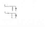
opened up my KEF iQ-3 and drew an schematic of what i found inside...
Cap voltages are 50/100V
Inductors have a quite thin wire, didnt get to measure dc resistance, but they sure look small.. one of them has an iron(ferrite?) core..
I'll try to get some pics of the crossovers and/or inside of the speakers online if someone wants them... Dont have my camera with me now...
I've been thinking about upgrading it...
I am no expert on crossover design nor parts selection, so i will apreciatte if anyone could give me some input...
I'm not really looking to change the values, maybe just change the nonpolar eletrolytics for some film caps, inductors with thicker wire maybe? air core also?
I can wind inductors myself, not sure if thats a good alternative...
Looking both for a sound upgrade and for the fun of doing it x)
Cheers all!
Attachments
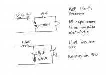
well, i wrote 6,8uF on the resistor on the drawing, but as you might figure, it was suposed to be ohms 😉
dont know how that happened... lol
p.s.: i do know the crossover "upgrade" has been talked about in the thread, i just find it a little confusing, so if i could have any more advice i'll be grateful
dont know how that happened... lol
p.s.: i do know the crossover "upgrade" has been talked about in the thread, i just find it a little confusing, so if i could have any more advice i'll be grateful
6uF or 5.6uF ?
Wes,
is that actually a 6uF capacitor in your iQ3, or is it a 5.6uF ?
5.6uF has been found in another iQ3.
How much of a hurry are you in to do your upgrade ?
I am working on an improvement to this crossover.
I can Post some suggestions for you now,
or, if you are not in a hurry I will Post the improvements when I have decided them.
But, please do check and Post whether 6uF or 5.6uF in your iQ3,
because this inormation will assist me to decide the improvement.
Hello honorable co-forumnists! 😀
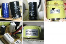
I'm sorry for all the confusion. I am now posting pics of the crossover with some drawings in an attempt to represent it more clearly.
If still that is not very easy to understand I can make another attempt.
alan-1-b,
Thanks for your reply. It is a 6uF capacitor, i have also measured it without taking it off the board and it says 6,03uF.
I am in no hurry at all. Actually i was also considering using a pre-amp as a crossover, and then bi-amping. Since good crossover caps and material for inductors isnt very easy nor cheap to find here, i thought maybe an active crossover would be a good option.
I am considering something like this design, but with a different frequency "cut".
Linkwitz-Riley Electronic Crossover
My only concerns are the following:
1- Which frequency cut would be satisfactory: 2500Hz, 2800Hz, other?
Honestly i dont know if i can test many...
2- I dont know if the inputs in the two speakers (tweeter and mid/bass) should be in the same voltage level. I am a little afraid of giving the tweeter amp the same gain as the mid/bass and kaputting it... (although I am using a pair of 7W amps with maximum peak to peak voltage of 15V - in reality much less - and I can say i wont be needing much more power... should i be worried of "overfeeding" the speakers?)
AndrewT,
Posting pics so u can confirm by yourself, just in case my readings and schematics are wrong. The day i did it i barely took the crossover off the speaker so... who knows eh 🙂
Measured the resistors without taking them off the board and they measure 1,5 Ohm and 7 Ohm.
Capacitors give a rather strange reading, but i think its because i didnt take them off the board too. 16uf and 15uF gave 3uF and 20 uF, dont know if respectively or not. If really needed I can unsolder them and measure.
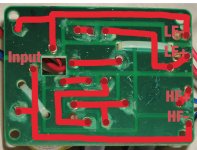
For the following pics I mirrored the image of the bottom of the pcb so that it would correspond to the component placement in the top of the pcb.
Other than that I had it skewed to correct the perspective of when i took the pictures. No other editing than those. Oh and the ugly drawings, of course! 😱
I'm sorry for all the confusion. I am now posting pics of the crossover with some drawings in an attempt to represent it more clearly.
If still that is not very easy to understand I can make another attempt.
alan-1-b,
Thanks for your reply. It is a 6uF capacitor, i have also measured it without taking it off the board and it says 6,03uF.
I am in no hurry at all. Actually i was also considering using a pre-amp as a crossover, and then bi-amping. Since good crossover caps and material for inductors isnt very easy nor cheap to find here, i thought maybe an active crossover would be a good option.
I am considering something like this design, but with a different frequency "cut".
Linkwitz-Riley Electronic Crossover
My only concerns are the following:
1- Which frequency cut would be satisfactory: 2500Hz, 2800Hz, other?
Honestly i dont know if i can test many...
2- I dont know if the inputs in the two speakers (tweeter and mid/bass) should be in the same voltage level. I am a little afraid of giving the tweeter amp the same gain as the mid/bass and kaputting it... (although I am using a pair of 7W amps with maximum peak to peak voltage of 15V - in reality much less - and I can say i wont be needing much more power... should i be worried of "overfeeding" the speakers?)
AndrewT,
Posting pics so u can confirm by yourself, just in case my readings and schematics are wrong. The day i did it i barely took the crossover off the speaker so... who knows eh 🙂
Measured the resistors without taking them off the board and they measure 1,5 Ohm and 7 Ohm.
Capacitors give a rather strange reading, but i think its because i didnt take them off the board too. 16uf and 15uF gave 3uF and 20 uF, dont know if respectively or not. If really needed I can unsolder them and measure.
For the following pics I mirrored the image of the bottom of the pcb so that it would correspond to the component placement in the top of the pcb.
Other than that I had it skewed to correct the perspective of when i took the pictures. No other editing than those. Oh and the ugly drawings, of course! 😱
Attachments
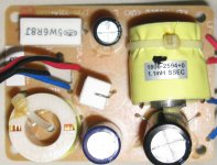
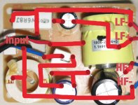
it looks like KEF have sourced some odd values of capacitors for this crossover. Presumably because KEF thought it was worth the effort.
Feeding the same voltage source to the crossover sends the correct voltage and frequencies to the respective drivers.
Bi-wire the speaker and again the same voltage source feeds both drivers.
Bi-amplify and you must use the same voltage to feed the crossover to ensure the correct voltage to the drivers.
Remove the crossover and all bets are off. You must measure and experiment to discover what voltages and what EQ each of the drivers needs, then you can design your active crossover for the active speakers.
- Status
- Not open for further replies.
- Home
- Loudspeakers
- Multi-Way
- kef IQ3 mod