gedlee said:That data doesn't really clarify anything to me other than it doesn't seem correct.
IIRC somewhere I read that all his measurements are done on axis in free field unless noted otherwise, but as it turned out, the data's probably not correct for a two way Unity since I erroneously remembered the C^3 being the prosound version when in actuality it's a three way variant, so I assume has a longer axial length and larger mouth, ergo control to a lower F.
Anyway, I asked TD to chime in re your missing data, etc..
GM
GM said:
since I erroneously remembered the C^3 being the prosound version when in actuality it's a three way variant, so I assume has a longer axial length and larger mouth, ergo control to a lower F.
GM
The C^3 uses the same basic horn as the Unities Nick sold through Lambda. (No corner fill though, which Nick's horn had) It is not a 3 way unity horn. The 10" drivers are on the outside of the enclosure and are not horn loaded.
Cheers
William Cowan
Attachments
So I did remember right, but then got confused reading the description on the SPL site, so the beamwidth plot should be valid then. 'Oldtimers' is a bitch. 🙁
Thanks for the clarification!
GM
Thanks for the clarification!
GM
cowanaudio said:(No corner fill though, which Nick's horn had)
There's been some comment on this by Tom, IIRC. But I wasn't clear on the conclusions, as an "issue" was referred to, but not really elaborated on. He seemed to indicate that the transition from driver to horn and circular to rectangular might be better without being "smoothed". I don't know if that applied to one or both transitions. What is the current state of knowledge?
Sheldon
G'day Sheldon
It's not a case of better or worse, they are just different and the crossover Tom developed for the C^3 was not suitable for the horns Nick was producing. The crossover on my webpage is the one Tom developed for Nicks version of this horn. This was done some time after the Unity kits were released and as far as I can tell few people with the kits have done the upgrade.
Note that the only difference between the two versions of this horn is the fillets in the corners that extend out to the mouth.
Cheers
William Cowan
Thanks,
One of these days I'll work on a passive crossover for the horn. Been avoiding it, as it's quite a challenge. I loaned out my copy of LspCAD and haven't gotten it back. On the other hand I was loaned a Tektronix 454 in return, which I've made good use of. Wouldn't be the worst thing to have to get a new copy.
Sheldon
nickmckinney said:Kapok cone ApolloTD15M that has a wee bit more xmax
Any info on these? 😀

Hi Guys
I should check in more I guess, thanks for the e-mail GM.
Well, I am glad you guys are interested in the Unity stuff, I was very pleased with these, however that was long enough ago that I don’t even have any working Unities like the C-3 anymore.
There has been approaching 10 years of improvement in design and understanding since then, enough refinements to warrant a second patent application under Synergy horn.
Dang Earl, I did promise I would take you those turntable measurements for you and haven’t forgotten. It seemed like a trivial thing with what I was planning but between mom being sick, work, going back to AES for a speaker thing (and I even renewed my membership too), summer evaporated.
I am not sure recording the pink noise while indoors would tell you much.
I still have some things I have to measure outdoors yet before snow and I’ll try to get the table etc set up then and drag out an SH-50.
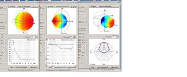
What one can get for now is the current design from the spherical data (the SH-50 CLF file) on line is shown in the screen capture below.
On top, you can see the radiation balloon at any angle by moving it around, you can see the balloon at any 1/3 oct center by selecting a new F.
Below, you can see the 6dB beamwidth graph or frequency response at any arbitrary angle (by moving the tabs that control the reference line in the balloon) or see H and V polar patterns at any 1/3 oct center F.
The other data is as shown by clicking the dots.
Max input Voltage, 56V was determined by increasing the pink noise test signal every 300 seconds until the system response shape, at any frequency, deviated 3dB from the 1W response shape.
This was a depression around 1KHz which is probably I^2*Rdc heating in the compression driver.
As the signal has a 6dB peak to average ratio, this takes an amplifier that can put out 112VRms.
All of these were independently measured; no way I could do these.
Sh-50 CLF file and viewer at;
http://www.danleysoundlabs.com/technical downloads.html
Ivan used the TEF at the shop to get the response on the product sheet, the 150Hz zone depression apparently a reflection in the warehouse, not windowed out by the TEF.
http://www.danleysoundlabs.com/pdf/SH 50 Spec Sheet.pdf
As a person who has spent most of his life building things and making speaker related sawdust, I am torn too between wanting to share the inner details as I see them now and the imperative to make our company as successful as possible and get my kids through College, the latter is an option I didn’t have but I sure don’t want them “to do it my way”.
I feel blessed to have found people like Mike and his guys to be involved with, they are good people, hard workers and committed and I absolutely don’t want to do anything that gives anybody that maters anything useful.
Also, being self-taught, one is always apprehensive to let others know how little you really know in a subject that just seems to have no end.
Sometimes your lucky and fate puts a twig in your path and a few steps later land in a place where an inquiring mind could ask some serious questions and learn .
On Pro-Sound web someone was asked about the Servodrive speakers, it was at Intersonics that things really changed for me.
Anyway, if interested, a post with sort of a history of those old days of Servodrives and Acoustic levitation..
http://srforums.prosoundweb.com/index.php/t/39819/0/
I have always been in awe of the few people like my old boss Dr. Rey and like Earl who “see math” and have apparently have a calculator in their head.
For me, math is an “Asian tattoo” on paper representing a semi imaginary machine , where if you get everything arranged just so, an answer in response to your variables comes out, viol the magic of math and computers.
In Mathcad I trust, when I can figure out how to make it do what I want.
This is as close as I have ever been able to get to seeing it like I design things, I see electronic circuits, electroacoustic systems, or mechanism’s, as a working “machines” in my head or on paper.
At one of my very first AES presentations on the Servodrive woofer, (where I was so nervous I used every drop of water provided), Earl was one of the people who stood up to ask a question at the end and I gulped and thought “Oh no what do I have wrong”. It wasn’t like that at all, he just asked a question about the inertia or something, phew.
Well, I will break this in two parts
Best,
Tom Danley
Part 2 follows
I should check in more I guess, thanks for the e-mail GM.
Well, I am glad you guys are interested in the Unity stuff, I was very pleased with these, however that was long enough ago that I don’t even have any working Unities like the C-3 anymore.
There has been approaching 10 years of improvement in design and understanding since then, enough refinements to warrant a second patent application under Synergy horn.
Dang Earl, I did promise I would take you those turntable measurements for you and haven’t forgotten. It seemed like a trivial thing with what I was planning but between mom being sick, work, going back to AES for a speaker thing (and I even renewed my membership too), summer evaporated.
I am not sure recording the pink noise while indoors would tell you much.
I still have some things I have to measure outdoors yet before snow and I’ll try to get the table etc set up then and drag out an SH-50.
What one can get for now is the current design from the spherical data (the SH-50 CLF file) on line is shown in the screen capture below.
On top, you can see the radiation balloon at any angle by moving it around, you can see the balloon at any 1/3 oct center by selecting a new F.
Below, you can see the 6dB beamwidth graph or frequency response at any arbitrary angle (by moving the tabs that control the reference line in the balloon) or see H and V polar patterns at any 1/3 oct center F.
The other data is as shown by clicking the dots.
Max input Voltage, 56V was determined by increasing the pink noise test signal every 300 seconds until the system response shape, at any frequency, deviated 3dB from the 1W response shape.
This was a depression around 1KHz which is probably I^2*Rdc heating in the compression driver.
As the signal has a 6dB peak to average ratio, this takes an amplifier that can put out 112VRms.
All of these were independently measured; no way I could do these.
Sh-50 CLF file and viewer at;
http://www.danleysoundlabs.com/technical downloads.html
Ivan used the TEF at the shop to get the response on the product sheet, the 150Hz zone depression apparently a reflection in the warehouse, not windowed out by the TEF.
http://www.danleysoundlabs.com/pdf/SH 50 Spec Sheet.pdf
As a person who has spent most of his life building things and making speaker related sawdust, I am torn too between wanting to share the inner details as I see them now and the imperative to make our company as successful as possible and get my kids through College, the latter is an option I didn’t have but I sure don’t want them “to do it my way”.
I feel blessed to have found people like Mike and his guys to be involved with, they are good people, hard workers and committed and I absolutely don’t want to do anything that gives anybody that maters anything useful.
Also, being self-taught, one is always apprehensive to let others know how little you really know in a subject that just seems to have no end.
Sometimes your lucky and fate puts a twig in your path and a few steps later land in a place where an inquiring mind could ask some serious questions and learn .
On Pro-Sound web someone was asked about the Servodrive speakers, it was at Intersonics that things really changed for me.
Anyway, if interested, a post with sort of a history of those old days of Servodrives and Acoustic levitation..
http://srforums.prosoundweb.com/index.php/t/39819/0/
I have always been in awe of the few people like my old boss Dr. Rey and like Earl who “see math” and have apparently have a calculator in their head.
For me, math is an “Asian tattoo” on paper representing a semi imaginary machine , where if you get everything arranged just so, an answer in response to your variables comes out, viol the magic of math and computers.
In Mathcad I trust, when I can figure out how to make it do what I want.
This is as close as I have ever been able to get to seeing it like I design things, I see electronic circuits, electroacoustic systems, or mechanism’s, as a working “machines” in my head or on paper.
At one of my very first AES presentations on the Servodrive woofer, (where I was so nervous I used every drop of water provided), Earl was one of the people who stood up to ask a question at the end and I gulped and thought “Oh no what do I have wrong”. It wasn’t like that at all, he just asked a question about the inertia or something, phew.
Well, I will break this in two parts
Best,
Tom Danley
Part 2 follows
Attachments
Part 2
Anyway, I will take a serious shot at describing “a horn” as I see it now, your mileage may vary.
To me a horn appears to have three general regions of interest.
Where impedance transformation takes place and ceases, where the directivity break point is, where the wall angle approximates / defines the radiation angle and the region between where the physical size vs frequency defines the radiation angle if the horn ended there.
For radiation efficiency, one finds that until you reach the plateau of the radiation resistance curve, the radiation resistance is a function of the acoustic size or physical size compared to wavelength involved.
For impedance matching, the idea of the exponential horn was that if the length and mouth was large enough, the horn would act as a broad band adaptive resonator.
To me it is pretty clear that it consists of two or more quarter wave stubs in series, that coupled the “larger area” flat plateau resistance to a physically tiny driver, greatly raising its efficiency.
A clear (I think) electrical analogue is a “T” network impedance matcher used for antenna’s.
Here, with only reactive elements, one can couple one resistive impedance to another impedance (over some bandwidth) by making the ground leg impedance of this resonator circuit the geometric median between the input and output.
For example coupling from 20 Ohms to 10 Ohms electrically requires the Tg leg to be 14.14 Ohms.
Take an exponential horn, cut it in half and you see the half way point has the same relation ship, here area is related to the impedance. Anyway you cut it, it has that geometry. Like the electrical analogue, the 3 element T network (half wavelength horn) can accommodate a much greater impedance variation or BW compared to the two element (quarter wavelength) network.
While the electrical circuit has reactance’s that are set by fixed electrical values and so has a specific bandwidth, the acoustic reactance’s vary in relation to the acoustic size, changing the frequency changes the reactance’s in a way that makes a horn a self adaptive “broad band” device (in perfect world), its resonant principal masked by its bandwidth and resistances, leaving a high pass / transformer.
For a bass horn, one usually can’t make the horn a half wavelength long and only one mode exists lower than that one, the quarter wave mode.
Here, one has a two element circuit and in a horn, one has the driver now located at /near the Motional minimum rather than the maximum like at 1/2 wl.
Also, being too far from the plateau dimension, one’s reactance’s are larger than the resistive elements can damp / mask.
The minimum Velocity at driver (closed ) end of the quarter wave resonance reflects through to motor Velocity in the impedance causing more current to be drawn, creating the lowest bump in the horns response and dip in impedance curve.
The quarter wave horn requires a driver that is totally different than what is desired for operation above the quarter wave mode.
For a fully “wideband” horn, one is hard pressed to make it big enough in the physical world and for now pretend one has a perfect driver. Lets say you did make a “proper” horn, one with a mouth that is about 1WL in circumference at the low cutoff.
At the low cutoff, all of the horn is used for impedance matching but an octave above, the impedance conversion stops well back from the mouth as higher up, the resistance plateau is reached at a smaller physical size.
Higher up in frequency the impedance conversion stops way inside the horn and the area near the mouth while not effecting impedance transformation, its size is defining the radiation angle at that frequency.
Even higher one finds the point where the horn’s wall angle and size are the governing factor in the radiation angle, along Don Keele’s pattern loss thumb rule.
For a one inch driver, at 20Khz, the impedance transformation region is well inside the driver and the exit size is large enough to be strongly defining the radiation angle.
At the very most (It appears to me), the best one inch compression driver’s geometry only allows one to coherently drive a horn of up to say 60 degrees and only if that angle is reached essentially immediately and driver with a diverging wavefront is used.. Obviously a 2 inch driver is about half that or less in practice.
I see a possible description of the HOM’s Earl discovered as internal reflections of diffraction, which occurs when one tries to abruptly bend a sound wave after its acoustic size is too large relative to the wavelength.
It seems that some drivers have a phase plug geometry, which produces a converging wave front at the summation, at an acoustic size, which imparts directivity, where actually the horn walls geometry wants to be driven with a diverging wavefront, forcing refraction.
For sure, this is not irresolvable, you can bend sound, you can bend 20KHz around and abrupt 90 degree bends with no IF the dimensions and geometry are suitable.
http://www.vtcproaudio.com/technology/paraline.html
AS the frequency climbs higher, the impedance transition point moves way back inside the horn and the directivity break point moves back inside the horn as well.
On an exponential horn this shift in control point up the horn, progressively confines the radiation about the center axis, while in a perfect Constant Directivity horn, nothing changes.
With the mid wall mounted driver, one sees several additional things.
To me, personally, I see one thing people ignore all the time, there is no point in trying to horn load a source or into a horn, who’s acoustic size is too large. How big is the throat compared to the highest frequency in question, is it pointless acoustically relative to the plateau region transition dimension?
To drive a horn in its impedance transformation region, one must be in an acoustically “small” part of the horn.
With many horn geometry’s one finds another effect which limits the high frequency response of a side mounted driver is that at some point, the driver is an acoustic quarter wave length from the point that is the effective “end” of the horn at that frequency, this cases a refection back to the driver which arrives delayed by two 90 degree passes and causes a small rise and then DEEP notch in the frequency response.
It was pondering that reflection that I eventually thought, “what happens if I substitute an out of phase source for the reflection?”, then like a transmission line, the two phases add at some frequency. By fiddling around modeling the acoustic configuration, there were occasional glimmers of “maybe something”. With a lot of time fiddling in the computer and nothing but the predicted results to go on, I did find some trends that lead to the first Tapped Horn products.
On all the speakers I make, the side mounted drivers connect to the horn passage through a Helmholtz low pass filter, made of the volume trapped under the cone and the mass reactance in the small port itself.
This is exactly like the Vented box except here, there is no direct radiation from the cone (one side is a sealed volume) and the operating frequency is always below the Fb instead of always above it with a vented box.
This way one has an acoustic second order low pass filter and a periodic self-cancellation in the horn, which produce a fairly steep total acoustical low pass filter effect somewhat above the normal operating band. This greatly reduces the harmonic distortion real drivers always produce.
For one range to cross into the other, one must have both ranges operating within the horn impedance transformation region, for multiple sources to combine such that they radiate as a single source out of the horn, the adding must take place where the dimensions are acoustically small and with the appropriate range of phase relationships.
In the case of the mid drivers, consider there are two small entry holes per driver so within the horn at the mid entry point, there are eight “in phase” sources located in less than a quarter wavelength circle in the horn, these add together coherently as eight “in phase” subwoofers do if they are located less than a quarter wavelength diameter circle.
Do this and the drivers’ act like one, radiate out the horn like one and down the horn as it gets larger IT governs the radiation angle.
AS one can see, the object for the side mounted drivers or the hf driver for that matter, is to produce what is functionally a point source, within its associated portion of the horn so that it becomes the larger dimension downstream of the horn (which continues at a fixed angle) that sets the radiation angle of a 50 by 50 degree spherical patch.
In the synergy horns, I was finally able to eliminate essentially all the “all pass” phase rotation that crossovers normally add by a combination of physical offset (time delay) and filter phase shifts using non-standard slope geometry’s.
This was finally pretty much what I was trying to achieve and it only took eight years to make them do it..
One last thought, with a plain conical horns like I use, one cannot make an asymmetric pattern, with out a proportional pattern. If you need an asymmetric pattern, make the difference between X and Y as small as possible, then pattern flip is as small as possible.
Often, our boxes are part of a system, here, where two or more horns are directly adjacent to each other, a square or rectangular horn actually works better combining into a summed pattern than round or oval horns do.
Anyway, I hope this fast, certainly incomplete overview helps shed some light on these horns.
Have a wonderful Thanksgiving everyone
Best,
Tom Danley
Danley Sound Labs
Sheldon said:
There's been some comment on this by Tom, IIRC. But I wasn't clear on the conclusions, as an "issue" was referred to, but not really elaborated on. He seemed to indicate that the transition from driver to horn and circular to rectangular might be better without being "smoothed". I don't know if that applied to one or both transitions. What is the current state of knowledge?
Sheldon
What we found if memory serves me correctly is the TAD driver response did not change with the corner fill but the B&C driver we were using at the time did. The TAD has a much longer throat than the B&C which might explain the difference.
fb said:
Any info on these?
Don't bother waiting for Kapok cone 15" Lambda drivers unless you want to buy a completed pair of cabinets. I will be possibly using them in my new home cabinets that I will release next year (I say possibly because the verdict is still out)
Tom as usual I will have to reread your posts about a dozen times before half of it soaks in
Patrick Bateman said:Last time I tried to build a Unity, I found that there aren't many drivers which are appropriate for a Unity horn. With some input from GM, I created a spreadsheet which tells you which midranges are appropriate. The optimum midrange is based on some specs from John Sheerin's webpage. There are a handful of midranges which are very VERY close.
The new Peerless 2 inch is almost perfect, if the published specs can be trusted. The B&C 6MDN44 is also very good, albeit expensive.
The "real" Unity uses a compression driver which is much larger than the one I like. Because of this, I prefer drivers which have a higher FS than Sheerin's ideal Unity.
Members of this club include the Ciare 6.38ndmr from Assistance Audio and the P-Audio/Winner WN-520N.
I'm happy to report that I've found a mid which is damn near perfect for my Unity project. A few years back I purchased a set of TangBand W2-852SC drivers. This is a two inch midrange. Darren Kuzma published a speaker that uses it's cousin, which has a poly cone and a phase plug. The W2-852SC is identical, except it uses a paper cone. Because it has a lighter cone with the same motor, it has a lower QMS and a higher FS, which is exactly what we want.
Unfortunately, the W2-852SC was discontinued.
Luckily, I ordered a batch of it's replacement, and they're even better! The W2-852SH looks similar to the 852SC, but uses a cast plastic frame. The cone must be lighter too, because the FS is much higher. But this is good news, it makes it an even better candidate.
I personally measured the T/S values of a batch; here are the averages:
TangBand W2-852SH
FS 192hz
QMS 4.28
QES 0.54
QTS 0.48
As mentioned earlier in the thread, I lost interest in finishing my 2nd attempt at a Unity for my car. I've been working from home for about four months now, and I drive about 1/10th as much as I used to.
I'm still a bit curious about a Unity for the home though.
Make no mistake, getting the midrange right is a complete p.i.t.a. In my first attempt to build a Unity, I evaluated half a dozen midranges, including models from Aurasound, Tang Band, JBL, and Audax.
It wasn't until GM responded to another poster that I realized the mids I used were wrong. They have excellent frequency response, but their not designed to play as high as we need them to in a Unity.
I even posted a spreadsheet of good candidates.
One problem with all the good candidates is that they're EXPENSIVE. For instance, there are nearly ideal candidates available now, but they cost about $100-$120 each. There's NO WAY I'm dropping $1000 on midranges alone.
One idea I had today was to simply "gamble" on a few cheap candidates which are so inexpensive, they don't even have specs published. Admittedly, they might be complete junk. But we might get lucky and find a candidate for under $50.
I wouldn't go this route if I were making a commercial product. In my opinion, I believe Sound Physics Labs, Yorkville, and Danley Sound Labs are all using drivers which were created explicitly for their products.
But we're just DIY guys, so we don't have the luxury of having a driver built for us. And I know you guys don't want to spend $1000 on midranges either!
There IS one known candidate for under $15. The Tangband W2-852SH has great specs for this application. As I see it, there are a few problems with the TB. It doesn't handle as much power as the mids that Danley chose. It has low efficiency. Possibly the biggest problem with the Tang Band midranges is that it's difficult to get consistent results. You have to put a cup on the Tang Band, and the tiniest variation in the cup's volume will screw up your response. The volume of the cup is SO TINY, it's literally impossible to get good results from the TBs unless you're using a very carefully sized enclosure.
Based on that, there are some attractive alternatives to the TB. I'll get to that in the next post.
Besides the woofers which I tried personally, I know that John Sheerin tried a few candidates.
Besides the MCM, John also tried a ferrite version of the Galaxy Audio woofer. IIRC, he tried a Parts Express woofer which is virtually identical to the MCM 55-1595.
Just for the hell of it, I took a different approach today. Instead of looking for a woofer which would work well in a Unity, I took a crack at trying to *guess* which woofer is actually used.
Chances are good both units are an OEM model. But you can examine pictures and guess who makes it. For instance, a Vifa woofer uses a distinctly different basket and terminal than a Eminence woofer.
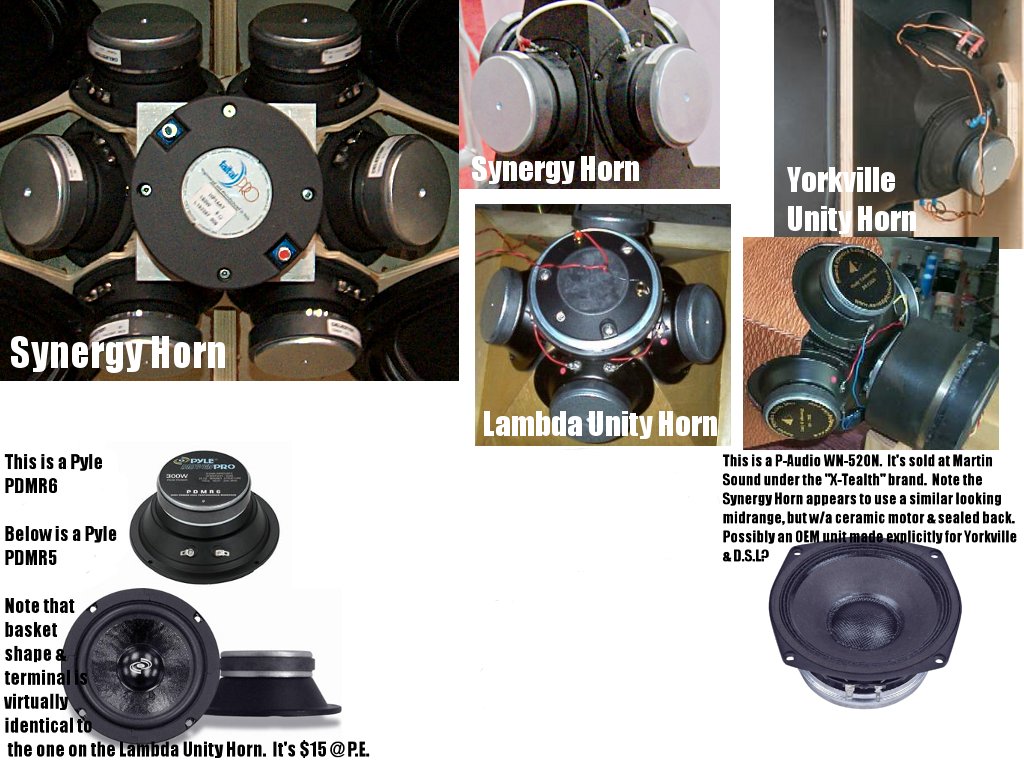
Based on my detective work, I feel about 90% confident that the original Lambda Unity midranges weren't made by Lambda. The LDSG says the midranges were made by Lambda Acoustics. But if you look at the basket and terminals, it's a dead-ringer for a Pyle pro sound midrange which is readily available from MCM and Parts Express. My hunch is that the WOOOFERS in the Lambda Unity were manufactured by Lambda, but the midranges are an OEM unit which was possibly used in the "real" Unity horn sold by Sound Physics Lab.
For those who are curious, I've also heard that they were made by Audax, and GM said an early prototype used a Fostex woofer.
The woofers in the Synergy Horn are a bit trickier. If you look at the basket, it's a distinctive semi-square shape. Looking at pics of the Yorkville unity, it certainly appears to use the same midrange. The magnet on the Yorkville Unity might be a little smaller, it's hard to tell.
I am not aware of ANY closed back midrange drivers which use a frame like this. I looked at everyone I could find, no luck. Having said that, the basket looks *suspiciously* like the P-Audio WN-520N. Doug Kelly clued me in to this woofer a few years back; it's an excellent candidate for a Unity horn. This is a stab in the dark, but I'm wondering if the Synergy Horn and Yorkville Unity horn share a midrange which is manufactured for them by P-Audio? That's the best guess I can come up with.
Danley uses BMS and Faital compression drivers; however these companies DO NOT offer a midrange with a basket that looks ANYTHING like what's being used in the Synergy Horn.
So that's my best guess. A variant of the Pyle PDMR5 in the original Unity, and a heavily modified variant of the P-Audio WN-520N in the Synergy horn. The PDMR5 is $15, and the WN-520N is nearly eight times as much.
The last thing I should note is that this makes the Synergy Horn an even BETTER buy than it already is. If it uses a thousand dollars worth of midrange drivers, I have NO IDEA how they're able to sell it at such a low price point.
Besides the MCM, John also tried a ferrite version of the Galaxy Audio woofer. IIRC, he tried a Parts Express woofer which is virtually identical to the MCM 55-1595.
Just for the hell of it, I took a different approach today. Instead of looking for a woofer which would work well in a Unity, I took a crack at trying to *guess* which woofer is actually used.
Chances are good both units are an OEM model. But you can examine pictures and guess who makes it. For instance, a Vifa woofer uses a distinctly different basket and terminal than a Eminence woofer.
Based on my detective work, I feel about 90% confident that the original Lambda Unity midranges weren't made by Lambda. The LDSG says the midranges were made by Lambda Acoustics. But if you look at the basket and terminals, it's a dead-ringer for a Pyle pro sound midrange which is readily available from MCM and Parts Express. My hunch is that the WOOOFERS in the Lambda Unity were manufactured by Lambda, but the midranges are an OEM unit which was possibly used in the "real" Unity horn sold by Sound Physics Lab.
For those who are curious, I've also heard that they were made by Audax, and GM said an early prototype used a Fostex woofer.
The woofers in the Synergy Horn are a bit trickier. If you look at the basket, it's a distinctive semi-square shape. Looking at pics of the Yorkville unity, it certainly appears to use the same midrange. The magnet on the Yorkville Unity might be a little smaller, it's hard to tell.
I am not aware of ANY closed back midrange drivers which use a frame like this. I looked at everyone I could find, no luck. Having said that, the basket looks *suspiciously* like the P-Audio WN-520N. Doug Kelly clued me in to this woofer a few years back; it's an excellent candidate for a Unity horn. This is a stab in the dark, but I'm wondering if the Synergy Horn and Yorkville Unity horn share a midrange which is manufactured for them by P-Audio? That's the best guess I can come up with.
Danley uses BMS and Faital compression drivers; however these companies DO NOT offer a midrange with a basket that looks ANYTHING like what's being used in the Synergy Horn.
So that's my best guess. A variant of the Pyle PDMR5 in the original Unity, and a heavily modified variant of the P-Audio WN-520N in the Synergy horn. The PDMR5 is $15, and the WN-520N is nearly eight times as much.
The last thing I should note is that this makes the Synergy Horn an even BETTER buy than it already is. If it uses a thousand dollars worth of midrange drivers, I have NO IDEA how they're able to sell it at such a low price point.
Patrick Bateman said:
For those who are curious, I've also heard that they were made by Audax, and GM said an early prototype used a Fostex woofer.
Hmm, I believe I said the early prototype used an Audax driver and that when I was looking for a replacement for someone since it was no longer available, I'd found a Fostex 'FR' driver that I thought looked good in a sim for a HIFI app, but the project was scrapped.
GM
GM said:
Hmm, I believe I said the early prototype used an Audax driver and that when I was looking for a replacement for someone since it was no longer available, I'd found a Fostex 'FR' driver that I thought looked good in a sim for a HIFI app, but the project was scrapped.
GM
Ah! Thanks for the clarification.
I'm tempted to buy some Pyle PDMR5s and measure them, to see if they'll work. I have a feeling they won't, because it has a "real" surround. Generally the surround adds too much weight to the cone in an application like this. That's why all the good candidates for a Unity horn midrange use a paper cone and a ribbed surround, instead of foam or rubber.
Pyle doesn't publish a figure for the FB. We want it above 400-500hz. That's very high for a 5" midrange of course.
The Pyle PDMW5 appears to be the same woofer, but with an open back. If the specs can be trusted, here's the figure for the Pyle:
fs/qes * 2 = 108/0.85 * 2 = 254hz
So it looks like another dud - it needs to have an FS which is higher 🙁
The reason that the P-Audio WN-520N works so well is that it has an insanely huge motor, which lowers the value of QES, and raises the FB.
Finding a good woofer for this project is a complete p.i.t.a.
I just went downstairs and dug out the midranges that I threw together for the Unity horn that was going to end up in my car. (Not the 1st one, the 2nd attempt.)
I removed the midranges and measured them. They're pretty darn good. I think they'll work better than the Pyle mids mentioned in the post above.
Maybe someone will spend a few bucks and measure the Pyle mids (buy a Pioneer closed back midrange while you're at it!)
At the moment, I think I'll stick with the TBs. My measurements show that they have an FB of 430hz in the spherical enclosures I built. That's about 100-150hz on the low side, but nothing I can't fix.
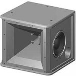
Here's a pic of the enclosures (I took them off the horn before I measured them.)

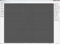
Attached is an impedance plot.
I removed the midranges and measured them. They're pretty darn good. I think they'll work better than the Pyle mids mentioned in the post above.
Maybe someone will spend a few bucks and measure the Pyle mids (buy a Pioneer closed back midrange while you're at it!)
At the moment, I think I'll stick with the TBs. My measurements show that they have an FB of 430hz in the spherical enclosures I built. That's about 100-150hz on the low side, but nothing I can't fix.
Here's a pic of the enclosures (I took them off the horn before I measured them.)
Attached is an impedance plot.
Attachments
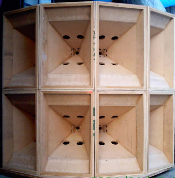
Some dude in The Phillipines built a bunch of unity horns:
http://www.flickr.com/photos/constantpressure/1371096992/sizes/m/in/set-72157601981699640/
http://www.flickr.com/photos/constantpressure/1371096992/sizes/m/in/set-72157601981699640/
FWIW, some time ago TD was pressured to divulge Unity design details on the HE forum. His response:
http://db.audioasylum.com/cgi/m.mpl...+%BC+inch+sealed+back+mid+drivers+tomservo&r=
GM
http://db.audioasylum.com/cgi/m.mpl...+%BC+inch+sealed+back+mid+drivers+tomservo&r=
GM
Hi Patrick
That the 5.25 inch mid driver was a “to my spec” part made by cone head Dan at Misco in Minneapolis. Your pyle sealed back mid would have a range where it should work this way however it has a heavier looking cone etc.
The 6 mid driver view, is for a larger speaker the SH96 which is a non array able speaker (these are at the Imax theater at Navy Pier Chicago for example), the 4 inch drivers are made to order by Celestion, can go up a little higher than the 5.25 but other wise serve the same purpose.
Hope that helps,
Tom
Tom Danley said:Hi Patrick
That the 5.25 inch mid driver was a �to my spec� part made by cone head Dan at Misco in Minneapolis. Your pyle sealed back mid would have a range where it should work this way however it has a heavier looking cone etc.
The 6 mid driver view, is for a larger speaker the SH96 which is a non array able speaker (these are at the Imax theater at Navy Pier Chicago for example), the 4 inch drivers are made to order by Celestion, can go up a little higher than the 5.25 but other wise serve the same purpose.
Hope that helps,
Tom
LOL, that's what I get for trying to play Sherlock Holmes!
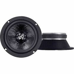
Here's a 5.25in woofer from Misco:
An externally hosted image should be here but it was not working when we last tested it.
Here's a 5in woofer from Pyle:
- Status
- Not open for further replies.
- Home
- Loudspeakers
- Multi-Way
- Another Unity Horn