Well, they certainly look like my Unity drivers.Patrick Bateman said:
LOL, that's what I get for trying to play Sherlock Holmes!
Here's a 5.25in woofer from Misco:
An externally hosted image should be here but it was not working when we last tested it.
Patrick Bateman said:
I spent some more time trying to optimize the holes.
In my last unity, i had a peak and a huuuuge null in the midranges. If anyone's curious, I can explain what I did wrong there. I figured it out yesterday, but haven't posted it yet.
Nonetheless, take a look at the attached pic, where I've tried to optimize the enclosure for the Tangbands. It looks like the peak is caused by using a compression ratio which is too agressive. When the throat (aka the holes) is big, the peak is reduced. Of course as the throat gets bigger, it begins to screw with the response of the compression driver.
I'm thinking it may be possible to have a relatively large peak in the midrange response, then null it out by placing the holes one quarter wavelength from the apex of the horn.
There's a glitch in my post from nine months ago. I fixed that this time around.
There are two problems. First, the volume of the front chamber is unreasonably small. If you look at the pic here, it's 53cc. That's for four drivers. With a 2in midrange, that works out to a front chamber that's a quarter of an inch deep!
Click on this URL to see the pic: http://www.diyaudio.com/forums/showthread.php?postid=1430966#post1430966
Basically that's impossible, because the volume under the cone itself is bigger than that.
OOPS.
That's why the response in the pic I posted nine months ago goes so high - it's unreasonably small.
The second problem is that I wasn't aware at the time that Horn Response can model a driver which is offset.
Here's some new (and better) models of my Tang Band mids for a Unity horn.
If you want to build this horn, here's the details:
#1 - This is a sixty degree conical horn. The mouth is 30" in diameter (twice as big as my Summas.)
#2 - The throat has a diameter of one inch.
#3 - There are four midrange holes. Each hole is located two inches forward of the apex, as measure on the EDGE of the waveguide. In other words, just get a ruler, measure out two inches from the side, and DRILL THE HOLE!
#4 - The waveguide holes are half an inch deep and half an inch in diameter. This is a huge deal, seriously. If you change the depth or the width, the whole design will go to hell. Modifying the diameter OR the depth modifies the shape of the midrange response. In other words, modify the holes at your own peril
#5 - The most important parameter of all is the impedance curve. We're dealing with VERY small volumes of air here kids; it's literally impossible to build this thing properly unless you can measure the impedance curve. The impedance curve will show you if you have leaks, it will show you if the volume of your chambers is wrong, and it will show you if the holes are sized properly. Basically I recommend that you modify the air volumes and the hole size until the impedance curve looks correct.
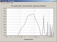
Attached is a pic of the predicted frequency response.
If you want to build this horn, here's the details:
#1 - This is a sixty degree conical horn. The mouth is 30" in diameter (twice as big as my Summas.)
#2 - The throat has a diameter of one inch.
#3 - There are four midrange holes. Each hole is located two inches forward of the apex, as measure on the EDGE of the waveguide. In other words, just get a ruler, measure out two inches from the side, and DRILL THE HOLE!
#4 - The waveguide holes are half an inch deep and half an inch in diameter. This is a huge deal, seriously. If you change the depth or the width, the whole design will go to hell. Modifying the diameter OR the depth modifies the shape of the midrange response. In other words, modify the holes at your own peril
#5 - The most important parameter of all is the impedance curve. We're dealing with VERY small volumes of air here kids; it's literally impossible to build this thing properly unless you can measure the impedance curve. The impedance curve will show you if you have leaks, it will show you if the volume of your chambers is wrong, and it will show you if the holes are sized properly. Basically I recommend that you modify the air volumes and the hole size until the impedance curve looks correct.
Attached is a pic of the predicted frequency response.
Attachments
Here's some new (and better) models of my Tang Band mids for a Unity horn.
If you want to build this horn, here's the details:
#1 - This is a sixty degree conical horn. The mouth is 30" in diameter (twice as big as my Summas.)
#2 - The throat has a diameter of one inch.
#3 - There are four midrange holes. Each hole is located two inches forward of the apex, as measure on the EDGE of the waveguide. In other words, just get a ruler, measure out two inches from the side, and DRILL THE HOLE!
#4 - The waveguide holes are half an inch deep and half an inch in diameter. This is a huge deal, seriously. If you change the depth or the width, the whole design will go to hell. Modifying the diameter OR the depth modifies the shape of the midrange response. In other words, modify the holes at your own peril
#5 - The most important parameter of all is the impedance curve. We're dealing with VERY small volumes of air here kids; it's literally impossible to build this thing properly unless you can measure the impedance curve. The impedance curve will show you if you have leaks, it will show you if the volume of your chambers is wrong, and it will show you if the holes are sized properly. Basically I recommend that you modify the air volumes and the hole size until the impedance curve looks correct.
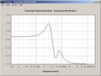
Attached is a pic of the excursion. Unfortunately we run out of excursion with five watts into each driver 🙁
Tom doesn't have to worry about competition, a two inch woofer isn't going to give his Synergy Horns a run for their money LOL
On the upside, the efficiency is well over 100db.
If you want to build this horn, here's the details:
#1 - This is a sixty degree conical horn. The mouth is 30" in diameter (twice as big as my Summas.)
#2 - The throat has a diameter of one inch.
#3 - There are four midrange holes. Each hole is located two inches forward of the apex, as measure on the EDGE of the waveguide. In other words, just get a ruler, measure out two inches from the side, and DRILL THE HOLE!
#4 - The waveguide holes are half an inch deep and half an inch in diameter. This is a huge deal, seriously. If you change the depth or the width, the whole design will go to hell. Modifying the diameter OR the depth modifies the shape of the midrange response. In other words, modify the holes at your own peril
#5 - The most important parameter of all is the impedance curve. We're dealing with VERY small volumes of air here kids; it's literally impossible to build this thing properly unless you can measure the impedance curve. The impedance curve will show you if you have leaks, it will show you if the volume of your chambers is wrong, and it will show you if the holes are sized properly. Basically I recommend that you modify the air volumes and the hole size until the impedance curve looks correct.
Attached is a pic of the excursion. Unfortunately we run out of excursion with five watts into each driver 🙁
Tom doesn't have to worry about competition, a two inch woofer isn't going to give his Synergy Horns a run for their money LOL
On the upside, the efficiency is well over 100db.
Attachments
Here's some new (and better) models of my Tang Band mids for a Unity horn.
If you want to build this horn, here's the details:
#1 - This is a sixty degree conical horn. The mouth is 30" in diameter (twice as big as my Summas.)
#2 - The throat has a diameter of one inch.
#3 - There are four midrange holes. Each hole is located two inches forward of the apex, as measure on the EDGE of the waveguide. In other words, just get a ruler, measure out two inches from the side, and DRILL THE HOLE!
#4 - The waveguide holes are half an inch deep and half an inch in diameter. This is a huge deal, seriously. If you change the depth or the width, the whole design will go to hell. Modifying the diameter OR the depth modifies the shape of the midrange response. In other words, modify the holes at your own peril
#5 - The most important parameter of all is the impedance curve. We're dealing with VERY small volumes of air here kids; it's literally impossible to build this thing properly unless you can measure the impedance curve. The impedance curve will show you if you have leaks, it will show you if the volume of your chambers is wrong, and it will show you if the holes are sized properly. Basically I recommend that you modify the air volumes and the hole size until the impedance curve looks correct.
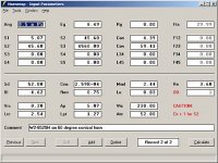
Attached is a pic of the horn response parameters. Note that these values are based on four of the TB woofers in series-parallel. If you built this yourself you'll have to divide the rear chamber and the front chamber volume by four. The model demonstrates that we're using a sixty degree conical horn, and the entrance holes measure 1/2" in diameter by 1/2" in depth (a total of four holes, one for each woofer.)
If you want to build this horn, here's the details:
#1 - This is a sixty degree conical horn. The mouth is 30" in diameter (twice as big as my Summas.)
#2 - The throat has a diameter of one inch.
#3 - There are four midrange holes. Each hole is located two inches forward of the apex, as measure on the EDGE of the waveguide. In other words, just get a ruler, measure out two inches from the side, and DRILL THE HOLE!
#4 - The waveguide holes are half an inch deep and half an inch in diameter. This is a huge deal, seriously. If you change the depth or the width, the whole design will go to hell. Modifying the diameter OR the depth modifies the shape of the midrange response. In other words, modify the holes at your own peril
#5 - The most important parameter of all is the impedance curve. We're dealing with VERY small volumes of air here kids; it's literally impossible to build this thing properly unless you can measure the impedance curve. The impedance curve will show you if you have leaks, it will show you if the volume of your chambers is wrong, and it will show you if the holes are sized properly. Basically I recommend that you modify the air volumes and the hole size until the impedance curve looks correct.
Attached is a pic of the horn response parameters. Note that these values are based on four of the TB woofers in series-parallel. If you built this yourself you'll have to divide the rear chamber and the front chamber volume by four. The model demonstrates that we're using a sixty degree conical horn, and the entrance holes measure 1/2" in diameter by 1/2" in depth (a total of four holes, one for each woofer.)
Attachments
Here's some new (and better) models of my Tang Band mids for a Unity horn.
If you want to build this horn, here's the details:
#1 - This is a sixty degree conical horn. The mouth is 30" in diameter (twice as big as my Summas.)
#2 - The throat has a diameter of one inch.
#3 - There are four midrange holes. Each hole is located two inches forward of the apex, as measure on the EDGE of the waveguide. In other words, just get a ruler, measure out two inches from the side, and DRILL THE HOLE!
#4 - The waveguide holes are half an inch deep and half an inch in diameter. This is a huge deal, seriously. If you change the depth or the width, the whole design will go to hell. Modifying the diameter OR the depth modifies the shape of the midrange response. In other words, modify the holes at your own peril
#5 - The most important parameter of all is the impedance curve. We're dealing with VERY small volumes of air here kids; it's literally impossible to build this thing properly unless you can measure the impedance curve. The impedance curve will show you if you have leaks, it will show you if the volume of your chambers is wrong, and it will show you if the holes are sized properly. Basically I recommend that you modify the air volumes and the hole size until the impedance curve looks correct.
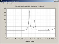
This is the most important graph of all, the graph of electrical impedance. If you build this horn, you MUST modify the front and rear volumes to produce the impedance curve illustrated below. A design like this is SO COMPLEX that you absolutely MUST tweak the variables until they match the model. The most important part of this graph is the trough between the peaks; this trough indicates where the enclosure is resonating.
If you want to build this horn, here's the details:
#1 - This is a sixty degree conical horn. The mouth is 30" in diameter (twice as big as my Summas.)
#2 - The throat has a diameter of one inch.
#3 - There are four midrange holes. Each hole is located two inches forward of the apex, as measure on the EDGE of the waveguide. In other words, just get a ruler, measure out two inches from the side, and DRILL THE HOLE!
#4 - The waveguide holes are half an inch deep and half an inch in diameter. This is a huge deal, seriously. If you change the depth or the width, the whole design will go to hell. Modifying the diameter OR the depth modifies the shape of the midrange response. In other words, modify the holes at your own peril
#5 - The most important parameter of all is the impedance curve. We're dealing with VERY small volumes of air here kids; it's literally impossible to build this thing properly unless you can measure the impedance curve. The impedance curve will show you if you have leaks, it will show you if the volume of your chambers is wrong, and it will show you if the holes are sized properly. Basically I recommend that you modify the air volumes and the hole size until the impedance curve looks correct.
This is the most important graph of all, the graph of electrical impedance. If you build this horn, you MUST modify the front and rear volumes to produce the impedance curve illustrated below. A design like this is SO COMPLEX that you absolutely MUST tweak the variables until they match the model. The most important part of this graph is the trough between the peaks; this trough indicates where the enclosure is resonating.
Attachments
Patrick Bateman said:
Basically that's impossible, because the volume under the cone itself is bigger than that.
Not impossible, you just have to use some form of reducing it as Tom does on at least one design.
GM
I just finished mocking up some drivers for woofer duty. It shouldn't be a big surprise that I used my "old standby" for the last octave. The good ol' MCM 55-2421.
So at this point this is what it looks like (on paper at least.)
High frequency: BMS 4540ND (1khz - 20khz) $120 (1)
Mid frequency: 4 x Tang Band W2-852SH (240hz-1khz) $58 (2)
Low frequency: 2 x MCM 55-2421 (80hz-240hz) $62 (3)
Basically it's an eight octave Unity horn, using $240 worth of drivers per side. Even with wood and crossover parts factored in, it should be do-able for under $375 per side. Efficiency should be in the neighborhood of 100db. We're basically limited by the compression driver This is due to the fact that we have to pad the BMS down to extend it's upper limit to 20khz.
(1) http://www.usspeaker.com/bms 4540-1.htm
(2) http://www.parts-express.com/pe/pshowdetl.cfm?&DID=7&Partnumber=264-808&ctab=2#Tabs
(3) http://www.mcmelectronics.com/product/55-2421
So at this point this is what it looks like (on paper at least.)
High frequency: BMS 4540ND (1khz - 20khz) $120 (1)
Mid frequency: 4 x Tang Band W2-852SH (240hz-1khz) $58 (2)
Low frequency: 2 x MCM 55-2421 (80hz-240hz) $62 (3)
Basically it's an eight octave Unity horn, using $240 worth of drivers per side. Even with wood and crossover parts factored in, it should be do-able for under $375 per side. Efficiency should be in the neighborhood of 100db. We're basically limited by the compression driver
This is due to the fact that we have to pad the BMS down to extend it's upper limit to 20khz.(1) http://www.usspeaker.com/bms 4540-1.htm
(2) http://www.parts-express.com/pe/pshowdetl.cfm?&DID=7&Partnumber=264-808&ctab=2#Tabs
(3) http://www.mcmelectronics.com/product/55-2421
I don't understand why you want to 'cripple' the design by using an HF driver with such poor HF response.
WRT the TB, in theory it seems to me that the extra effort to deal with the protruding DC would be more trouble than it's worth. What might be entertaining though as an ultra cheap entry level design is to use this driver in a 1" throat Unity or Summa concept WG with the DC as a mini phase plug. Efficiency would suck by HE standards, but be no worse than what most folks listen to anyway.
GM
Patrick Bateman said:I just finished mocking up some drivers for woofer duty. It shouldn't be a big surprise that I used my "old standby" for the last octave. The good ol' MCM 55-2421.
So at this point this is what it looks like (on paper at least.)
High frequency: BMS 4540ND (1khz - 20khz) $120 (1)
Mid frequency: 4 x Tang Band W2-852SH (240hz-1khz) $58 (2)
Low frequency: 2 x MCM 55-2421 (80hz-240hz) $62 (3)
Basically it's an eight octave Unity horn, using $240 worth of drivers per side. Even with wood and crossover parts factored in, it should be do-able for under $375 per side. Efficiency should be in the neighborhood of 100db. We're basically limited by the compression driver
(1) http://www.usspeaker.com/bms 4540-1.htm
(2) http://www.parts-express.com/pe/pshowdetl.cfm?&DID=7&Partnumber=264-808&ctab=2#Tabs
(3) http://www.mcmelectronics.com/product/55-2421
The BMS datasheet shows 110db sensitivity past 20khz in a 90x75 CD horn, is the datasheet wrong or is the 10db loss because you have a much larger conical horn?
GM said:So you're saying you find its deep, wide BW notch acceptable?
GM
No, I can`t say that I do. But the notch is 5db, not 10db.
True if you only EQ the horn to the 110 dB mark, but the resulting 5 dB notch over such a wide BW is unacceptable to me and apparently PB too.
As always though, YMMV.
GM
As always though, YMMV.
GM
GM said:I don't understand why you want to 'cripple' the design by using an HF driver with such poor HF response.
WRT the TB, in theory it seems to me that the extra effort to deal with the protruding DC would be more trouble than it's worth. What might be entertaining though as an ultra cheap entry level design is to use this driver in a 1" throat Unity or Summa concept WG with the DC as a mini phase plug. Efficiency would suck by HE standards, but be no worse than what most folks listen to anyway.
GM
When I tried to clone a Unity the first time I used the BMS 4540nd for one reason and one reason only -
It's tiny.
In the process I discovered that it sounds excellent. The first thing you notice about the BMS is that it's capable of playing higher than any compression driver I've heard.
For example, when compared to a B&C DE25, they're both down 3db at 10khz. But the B&C drops off a cliff around 15khz, whereas the BMS has output out to 25khz.
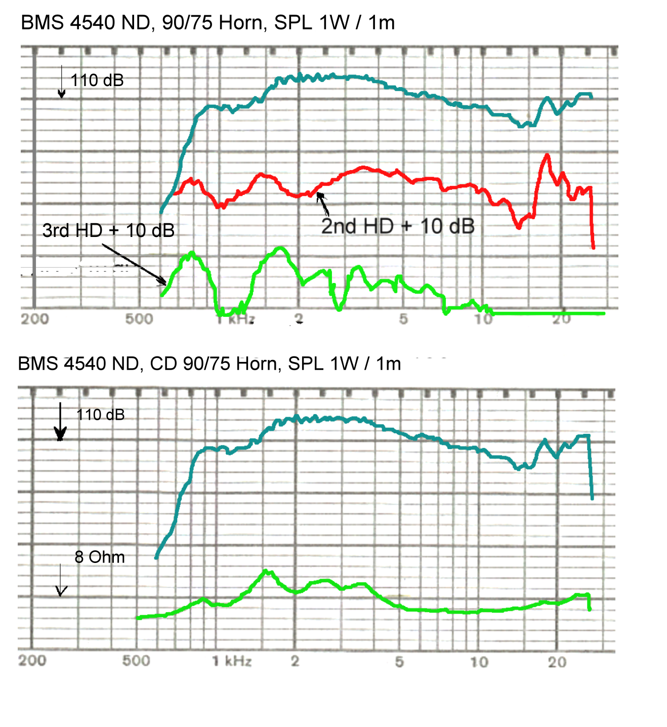
Here's the published response graph of the BMS 4540ND:
An externally hosted image should be here but it was not working when we last tested it.
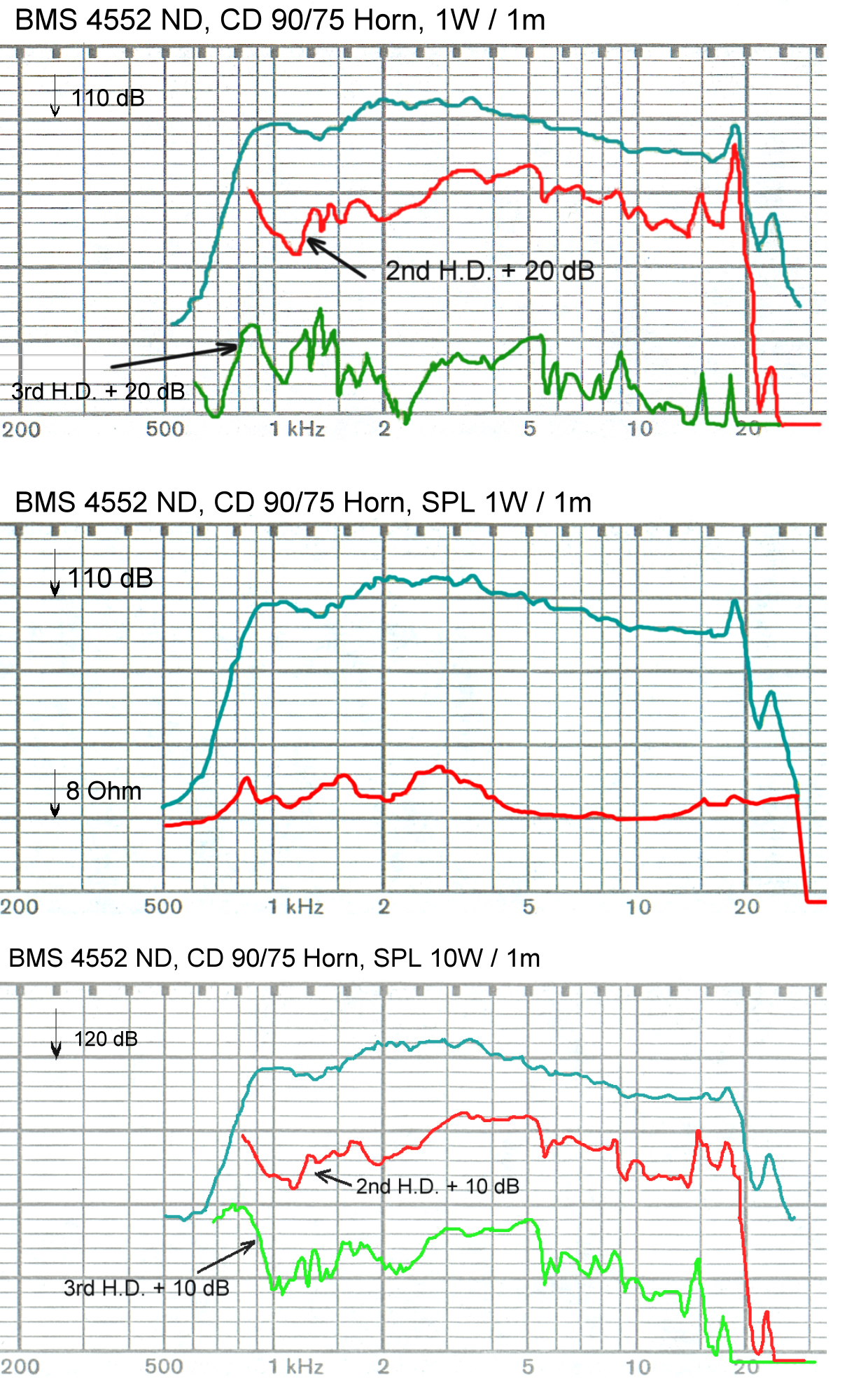
Here's it's big brother, the 4552ND. Note there's a resonance which is lower in frequency:
An externally hosted image should be here but it was not working when we last tested it.
I measured the BMS 4540ND myself when I used it for my Unity clone in 2006. My measurements showed that it had a gradually falling response, with no big peaks. This made the passive crossover very easy to design, particularly since the HOM-killing foam subtracts a few db on the top end. I don't have my graphs handy, but here's a measurement on an 18sound waveguide. Note that it has "real" output past 20khz:
That alone isn't sufficient to explain why the BMS sounds so damn sweet. I think there's another factor worth considering. As I understand it, compression drivers take advantage of a diaphragm resonance to extend their upper frequency response. If the resonance was damped, a compression drive would run out of steam around 10khz. By using the resonance to extend the response, we can get 18khz out of a B&C DE25, even though it's diaphragm is three inches across. That's amazing performance for such a large diaphragm, right?
Now if you look at the BMS, it has the same resonance BUT it's much higher in frequency. The BMS has output to 25khz. It's reasonable to assume that both compression drivers have a diaphragm resonance, but the resonance in the BMS appears half an octave higher in frequency.
The bottom line is that the BMS plays higher, and sounds "sweeter" to my ears.
GM said:So you're saying you find its deep, wide BW notch acceptable?
GM
There is no deep, wide notch!
BMS measures its 1" drivers on a RCF H100 Horn. This horn is near CD up to 15kHz, above it starts beaming.
The frequency response of the 4540 on a CD-Horn
An externally hosted image should be here but it was not working when we last tested it.
GM, Thanks for taking the time to answer 🙂
Another thing.... I can see there is a sharp rise in 2.harmonic distortion starting just above 15khz following the rise in sensitivity. Is the higher sensitivity above 15khz caused by resonances?
Regards,
Peter
Still learning...
*edit* gto my questions answered while I was typing.
Thanks jogi59 and Batman*
I hit paydirt!
The closest thing to an oblate spheroidal horn which is widely available is the DDS Eng 1-90 waveguide. It has a 90 degree coverage angle (hence the name.)
Over on Lansing Heritage I found someone who has measured a JBL 2407H on this rather excellent waveguide.
Now what the heck does a JBL 2407H have to do with this discussion you ask?
Well it's basically the same compression driver as the BMS 4540ND
The graph shows output to an astonishing 40khz, which seems all but impossible. But there it is:

This graph above is the closest comparison I can make to my existing system (Summas) without actually tearing them apart. (Which I'm not going to do!!!)
The published graphs show that the compression driver is down 10db at 20khz, and 3db at 17khz on it's 90 degree waveguide:
The closest thing to an oblate spheroidal horn which is widely available is the DDS Eng 1-90 waveguide. It has a 90 degree coverage angle (hence the name.)
Over on Lansing Heritage I found someone who has measured a JBL 2407H on this rather excellent waveguide.
Now what the heck does a JBL 2407H have to do with this discussion you ask?
Well it's basically the same compression driver as the BMS 4540ND
The graph shows output to an astonishing 40khz, which seems all but impossible. But there it is:
This graph above is the closest comparison I can make to my existing system (Summas) without actually tearing them apart. (Which I'm not going to do!!!)
The published graphs show that the compression driver is down 10db at 20khz, and 3db at 17khz on it's 90 degree waveguide:
An externally hosted image should be here but it was not working when we last tested it.
jogi59 said:
There is no deep, wide notch!
BMS measures its 1" drivers on a RCF H100 Horn. This horn is near CD up to 15kHz, above it starts beaming.
Then how do you explain their published plot that PB posted?
GM
Hi Guys,
It's worth mentioning that often the response of a one inch driver around 5-10K is strongly dependent on the shape of the horn immediately past the driver exit. I described this more in the horn writeup.
As this part of the horn is setting the radiation pattern up high.
While it might be mechanical, I wouldn't be surprised to see that notch feature turn out to change or even go away on a different horn. If that were the case, then one could probably find a set of Earls HOM's associated with that notch feature.
Best,
Tom
Patrick Bateman said:
It's tiny.
The first thing you notice about the BMS is that it's capable of playing higher than any compression driver I've heard.
Note that it has "real" output past 20khz:
That alone isn't sufficient to explain why the BMS sounds so damn sweet. I think there's another factor worth considering. As I understand it, compression drivers take advantage of a diaphragm resonance to extend their upper frequency response. If the resonance was damped, a compression drive would run out of steam around 10khz.
The bottom line is that the BMS plays higher, and sounds "sweeter" to my ears.
True, and for your car app a 'no-brainer' choice, though for true HIFI I'm not so sure.
Right, though its 'real' output is nothing more than break-up modes plus suspension resonances (noise) which is true of any compression driver AFAIK. Indeed, pretty much from day one the surround was designed to extend a compression driver's perceived HF response, so WRT the 4540 we have two things 'at play' compared to other 1" exit drivers, a smaller VC diameter which doesn't roll off as low as a larger one and has a lower compression ratio. The trade-off though is less damping as shown in both its response and 2nd harmonic distortion plots compared to the overall more benign 4552. Not many 'free lunches' in audio.
Can't comment about how it sounds since even if I auditioned one my old, well abused ears can't hear anywhere near that high anymore 🙁, but as a matter of good engineering I'd want to flatten its response as much as practical, which means a lot of attenuation if one wants it ~flat to at least 20 kHz. Frankly, I'd rather BW limit a different driver's HF noise and use a bone fide super tweeter horn to keep efficiency high since I've yet to meet anyone whose HF hearing can tell it's physically separate from a mids/HF horn, especially if stuck in its mouth and delayed.
As always though, YMMV.
GM
- Status
- Not open for further replies.
- Home
- Loudspeakers
- Multi-Way
- Another Unity Horn