You were right, the gate was floating. I used to have a voltage dividing pot there, but disconnected it.
Now, after I connected the gate to ground via 1.5M resistor, the voltage was 5.5V at the gate, higher, but still isn't where we want it (around 1/2 of the 24V)
The Voltage across the Darlington now is around 18.7V, across the NPN 0.2 Volts.
Could you tell me what those numbers tell you and why? I probably should give up on the transistors and replace them now, correct?
I am learning a bunch here. I should have started asking questions at forums earlier. Thank you a lot!
If you are unsure over the two NPN transistors being OK, then isolate the base of the darlington (or remove it completely from the circuit). The Drain of the FET should now be at the required 12 volts... but... FET's have a pretty wide tolerance and so I suspect that this could be more a case of something like that going on rather than a failed device.
Fig #1 in your link shows just the FET without the buffer stage. The drain should be 12 volts give or take.
Voltages tell all") 18.7 across the darlington means it is being biased into conduction just a little such that the emitter voltage is beginning to rise.
18.7 across the darlington means it is being biased into conduction just a little such that the emitter voltage is beginning to rise.
Fig #1 in your link shows just the FET without the buffer stage. The drain should be 12 volts give or take.
Voltages tell all
18.7 across the darlington means it is being biased into conduction just a little such that the emitter voltage is beginning to rise.Mooly, you saved the life of 2 perfectly fine transistor. I discovered the wrong resistor snuck into the drain position of the Jfet.
Now things seem to line up:
V at Jfet drain: 16V - good enough for now
V across the 100 Ohm resistor: 9.6V
Current: 0.096A
V across Darlington: 8.33V ~ 0.8W
V across the NPN: 6.49V ~ 0.6W
So, no transistors broken, and I definitely need that heatsink.
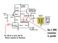
Adason: I will also double up on the NPN transistor. I have never seen this done before, but then there are many things I haven't seen, yet.
Thank you both. I will give you an update here once I get everything cleaned up.
Cheers, Chris
Now things seem to line up:
V at Jfet drain: 16V - good enough for now
V across the 100 Ohm resistor: 9.6V
Current: 0.096A
V across Darlington: 8.33V ~ 0.8W
V across the NPN: 6.49V ~ 0.6W
So, no transistors broken, and I definitely need that heatsink.
Adason: I will also double up on the NPN transistor. I have never seen this done before, but then there are many things I haven't seen, yet.
Thank you both. I will give you an update here once I get everything cleaned up.
Cheers, Chris
Mooly, you saved the life of 2 perfectly fine transistor.
That's good
I must admit that this design seems a little too dependent on the actual transistors (their individual characteristics) to be reliably reproducible... well that's how it seems.
Its certainly tweakable on an individual basis though to get it to work correctly.


Wow, that is a difference. How would I go about correcting for that? Set it up on the breadboard and then adjust by changing R3 and R6?
I am also wondering what the desired voltages would be. Do we even WANT exactly 12V at the drain of the Jfet, since we are aiming for asymmetric clipping/even harmonics (or does that not make any sense?)
Speaking of which, Scott in the article mentions that the 50 Ohm resistor at the source in series with the cap and resistor will get us more even harmonics. I couldn't find anything about why that would be. Do you, or someone, have an idea?
If you remove the darlington you can tweak R3 to give around 13 or 14 volts on the drain. Refit the darlington and that should give around 12 volts at the output. Now tweak R6 to give the 40ma desired in the 100 ohm.
Symmetrical clipping... give me a minute and I'll try it.
Symmetrical clipping... give me a minute and I'll try it.
Last post for today
So... the clipping is definitely assymetric even when overdriven grossly. You can see the waveform taking on the classic look of lots of second harmonic distortion. You can see the DC voltages I set up for this.
And here is the FFT plot with the amplitude reduced below obvious clipping.


It would be interesting to try and optimise it at lower levels... one for tomorrow maybe.
So... the clipping is definitely assymetric even when overdriven grossly. You can see the waveform taking on the classic look of lots of second harmonic distortion. You can see the DC voltages I set up for this.
And here is the FFT plot with the amplitude reduced below obvious clipping.
It would be interesting to try and optimise it at lower levels... one for tomorrow maybe.
chvario, if you get tired of hamptone, here is something which works for sure, I built numerous variations of this circuit
http://blog.audioworkshop.org/simple-jfet-preamp/#.VunHld7D-Uk
http://blog.audioworkshop.org/simple-jfet-preamp/#.VunHld7D-Uk
The one adason posted looks much better at a quick glance. It should be far more reproducible and with more consistent results. Another major disadvantage to the first one is that the gain is somewhat dependent on the individual FET used which is not good.
Ideally a (simple) circuit like these should work consistently well with pretty much anything you throw at it parts wise.
Ideally a (simple) circuit like these should work consistently well with pretty much anything you throw at it parts wise.
I am not too worried about different gain using different jfets, since I have been measuring and matching jfets using the runoffroove technique and calculator from their article on the Fetzer Valve. I know that given that that design is slightly different, the gain won't be the correct number, but it will give me relative comparison.
But could you explain how is it that the one Adason shared is NOT dependent on the individual jfet? Is that because of the feedback?
But could you explain how is it that the one Adason shared is NOT dependent on the individual jfet? Is that because of the feedback?
Well I threw this one into the simulator as well and it's perhaps not quite as 'good' as I first thought. The gain is still a little FET dependent which is a concern when you need to build a stereo pair. You want both channels to be the same.
This shows the distortion for 1 volt rms output into a 100k load.


This shows the distortion for 1 volt rms output into a 100k load.
Thank you.
It's not going to be stereo. I am going to do 2 channels, but it actually wouldn't be too big a problem if they don't have the same gain, even if they sound slightly different. I want to use these to give recordings a bit of coloring/saturation/distortion.
You got me interested in LTspice and it's FFT implementation. I didn't know that existed. I followed that link about "Installing and using LTspice". Is that post going to be helpful for Mac users as well?
I think if you go to the LT site there is a MAC version listed... just looking. Yes there is,
Linear Technology - Design Simulation and Device Models
How it would appear on a MAC I couldn't say but I guess it will be very similar.
If you want a bit of colour in your recordings then I think either of these two would fit the bill. I'll attach the LT spice file of the preamp as it stands now and then if decide to have a play you have a head start.
Attachments
- Status
- This old topic is closed. If you want to reopen this topic, contact a moderator using the "Report Post" button.
- Home
- Live Sound
- Instruments and Amps
- Hamptone JFET mic pre help!