You're very welcome 🙂 and I think you will find seeing how it all behaves in simulation quite interesting.
Hello,
I hope i will not sound rude without proper introduction, as it would be a long story so i would like to instead get right to the point.
As my first microphone preamplifier project at first i selected the one from Scott Hampton in regard to the tapeop article.
Then i stumbled on this thread so instead decided to take on the second schematic from adason post because that one was even more simple so i could focus on quality parts instead.
well, after some time trying to troubleshoot myself; am having some annoying problems. It seems i cannot get 7V on the collector of BC560C (i keep getting 0.612V) so in turn i cannot get requiered 1.8V on the source of BF245B (here i am seeing 0.535V).
The only voltage which is more ore less around the reference from the schematic is the one on the drain which in my case reads 11.73V.
I hope somebody will see this on as i am aware this is a 2 year old thread but any suggestions would be appreciated as i am running out of ideas how to get this preamp working as it should.
Thanks
...without proper introduction
...at first i selected the one from Scott Hampton
...instead decided to take on the second schematic from adason post
...well, .... It seems i cannot get 7V on the collector of BC560C (i keep getting 0.612V) so in turn i cannot get requiered 1.8V on the source of BF245B (here i am seeing 0.535V).
The only voltage which is more ore less around the reference from the schematic is the one on the drain which in my case reads 11.73V.
...I hope somebody will see this on as i am aware this is a 2 year old thread...
There's 400,000 members here; nobody waits to be "introduced". But there is an Introductions section.
We see it because you bumped it to the top of the section list.
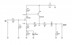
It may get little reply because it is not clear *what* you are building. Not the Hampton? Adason posted a small image in reply #22... that one, not that one?
You mention BC560; I don't think either Hampton or Adason #22 use a '560.
Adason also posted a link to an external blog, and that does have a '560.
That one?
The "11.4V" at Q2 Base is very specific. Actually it MUST be 0.6V down from the "+12V" line (whatever it really is). Your readings suggest Q2 is "off", which means Q1 is also "off", which means a bad connection, wrong value somewhere, or an unhappy pick of devices (maybe a mis-read of transistor pin-out).
Mark ALL the voltages, post the image or list, and maybe someone here can spot the error.
Attachments
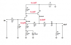
Here are my voltages.
Q2 is BC560B and so i read its pin-outs according to motorola datasheet.
Q1 is BF245B and i checked the pin-outs also according to the datasheet.
Q2 is BC560B and so i read its pin-outs according to motorola datasheet.
Q1 is BF245B and i checked the pin-outs also according to the datasheet.
Attachments
Last edited:
As PRR said, Q1 is nearly "off" (from the source voltage you measured, it's only flowing about 230 micro amps of source current).Here are my voltages.
Since Q1 is a depletion-mode JFET, it should not be off - this circuit relies on Q1 flowing more than enough current to turn on Q2, which is currently not happening.
(If Q1 were operating properly, Q2 would turn on, and "throttle down" Q1 until everything settled into proper balance.)
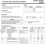
The question is, why is Q1 nearly off? I looked up the datasheet, and the magnitude of Vgs_off for the BF245 can be as small as 0.25 volts (see attached image.)
Although the particular JFET you happent to be using isn't quite this bad (we know Vgs_off is bigger than 0.53 V), the problem is now clear.
This particular JFET type (BF245) isn't, as PRR suggested, a "happy match" to the other component values in this particular circuit.
This is easily fixed, however. You need to either dial R5 down (try using a 4.7k trimpot rather than a fixed 2.2k resistor), or dial R3 up (again, use a 4.7k trimpot rather than a fixed 2.2k resistor here.)
In either case, tweak the trimpot until Q2 collector settles at a reasonable value, i.e. somewhere in the vicinity of 6 volts (half of the 12 volt supply voltage.)
JFETs have enormous parameter spreads, and this makes it quite tricky to make a "one size fits all" JFET circuit. I don't know anything about the designer of this particular circuit, but often JFET circuits like this are designed by poorly informed hobbyists, who don't realize how wide JFET parameter spreads are, and take no steps at all to address this in their designs. If this happens, you end up with a circuit that only works some of the time, even if built correctly according to the schematic.
-Gnobuddy
Attachments
Thanks for the reply and explanation. I swapped R3 with a 1M trimmer which only gave me 4.33V on Q2 collector. I had to use a trimmer on R5 also and dialing that one down to 1k got me to 6V Q1 source. Will post my voltages in a couple of minutes.

The voltages look good, but I can't make any sense of the 1M resistor. You should have been able to get the 6V collector voltage with far, far, far less resistance than 1M. 😕Here are my new voltages
Did you by any chance measure that 1M trimpot before installing it, to see if it is actually 1M? (Don't bother measuring in-circuit, the base-emitter junction of Q2 will almost certainly make nonsense of any resistance measurement.)
At any rate, despite the mystery of the 1M pot, your circuit should work now, so happy days!
-Gnobuddy
The voltages look good, but I can't make any sense of the 1M resistor. You should have been able to get the 6V collector voltage with far, far, far less resistance than 1M. 😕
Did you by any chance measure that 1M trimpot before installing it, to see if it is actually 1M? (Don't bother measuring in-circuit, the base-emitter junction of Q2 will almost certainly make nonsense of any resistance measurement.)
At any rate, despite the mystery of the 1M pot, your circuit should work now, so happy days!
-Gnobuddy
Yes i did measure all of trimpots before soldering them in R3 position (i have tried everything from 5k-1M). 1M measured on my multimeter 0.944 so it is 1Megaohm. It was also very strange to me that i needed that high resistance as opposed to the schematic and per your suggestion only to squeeze out 4.30V total.
During the trimpot swapping i did test the circuit and it was interesting to see how it reacted like a valve cathode bias would. At 1.5volt it was funcioning but the sound was so forward and dirty as hell and as i stepped up the voltage is started to get tight. Almost like when i bias my valve amplifier.
Gnobuddy, thank You for the writeup and help. You have written interesting stuff and if it were not for your pointing toward R3 and R5 who knows how long would it take me to figure it out.
Now i only need to figure out if i have wired the input transformer correctly for 1:12.9 ratio and figure out how to terminate it. This is the only confusing part left and i feel i am missing some low end out of this preamp.
The problems all come from the fact that Q1 is very different from the originally specified 2N3819. The BF245 wants much less DC voltage between source and gate to turn itself off, and also flows much less current to start with.It was also very strange to me that i needed that high resistance
Reading through your newest results, I underestimated the effect of R6, which raises the voltage at the source of Q1. With a 2N3819 you'd have been fine, but with the BF245, that voltage is enough to turn off the BF245 completely when Q2 collector is at 6 V!
So that's why you ended up lowering R5 down to 1k. That reduced the DC voltage fed back to Q1 source from Q2 collector, and that in turn allowed Q1 to just barely start to flow the teeny-weeniest bit of current. So little current, that you had to increase R3 to a crazy 1 Meg to get Q2 to turn on properly.
So now your circuit is working, but Q1 is still almost completely shut down.
If you're happy with the way it's working now, no need to change anything. But if it's overloading too easily, or distorting more than you want, we can make more changes to get Q1 to flow a bit more current.
If you do decide to change things, I would try replacing R4 with 270 ohms, and R6 with 33k. These changes will keep the voltage gain about the same, but drop the DC voltage at Q2 source, and allow Q2 to flow a bit more current. That in turn should allow you to reduce R3 to a more reasonable value. R5 should still allow you to set Q2 for 6V on the collector.
You're right, transistor circuits also need to be biased properly to work. Most modern transistor circuits are designed in such a way that they automatically bias up properly. But the JFET preamp you're dealing with is (a) a vintage design, (b) uses a JFET, which always means wide manufacturing tolerances, (c) uses the wrong JFET, i.e. not the original part number intended to be used, (d) may have been designed by someone who did not take into account the effect of wide manufacturing tolerances in JFETs....as i stepped up the voltage is started to get tight. Almost like when i bias my valve amplifier.
So using a BF245 in place of a 2N3819 is a bit like stuffing a 12AX7 triode where an ECC99 was supposed to go - you'll need to adjust your bias resistors bigtime to make it work at all, because the two tubes are so different.
You're very welcome!Gnobuddy, thank You for the writeup and help.
I estimate that the schematic you posted has bandwidth down to 2 Hz or so - no lack of low end there.Now i only need to figure out if i have wired the input transformer correctly for 1:12.9 ratio and figure out how to terminate it. This is the only confusing part left and i feel i am missing some low end out of this preamp.
So if you're hearing lack of bass, it probably does come down to the transformer, and/or the way it's currently wired.
Can you show more of the schematic, i.e. how the transformer is connected, and what transformer you are using? Perhaps I can help if I can see what you're actually doing.
-Gnobuddy
Great ! Yes, i would like to work some more on this one before i put a lid on the chassis. Let us discipline it further.
I will replace the resistors per your suggestion because currently for the purpose of guitar cab micing; in my opinion, the circuit distorts too easily (i dont know how quick jfet mic preamps distort as this is my first hand experience). For vocals it sounded right even with low voltage through Q2 but too saturated and quick for a low volume amp setting.
As for the input transformer; i am using OEP A262A3E
http://docs-europe.electrocomponents.com/webdocs/10fb/0900766b810fb25c.pdf
I wired primaries in parallel and secondaries in series which i "think" would/should result in a step up ratio 1:12.9. Not sure with what values to load primary and secondary (maybe 150R in series with signal at the primary and 250k secondary ?)
Output transformer is Edcor WSM600/600 (nothing confusing with this one)
... ...I would try replacing R4 with 270 ohms
....bandwidth down to 2 Hz or so ...
My mental math suggested 390r at R4. But whatever works.
The 1uFd output cap is marginal for modern 10K inputs: -3dB@16Hz, -1dB@32Hz. I actually do not think this is a problem..... the one recording I did which had 32Hz music had far larger errors in room and mikes. But it wouldn't cost a dime to throw 10uFd there.
Guitar cabs are usually very, very loud. A mic right in front of a loud guitar cab can put out a really big signal - so big that it can actually be line level:...for the purpose of guitar cab micing...the circuit distorts too easily
(That was taken from Can a dynamic microphone handle really loud sounds? (Maximum SPL) | Knowledge Base | Shure Americas )For the SM58, the frequency range to first exhibit distortion is centered around 100 Hz, close to the resonant frequency of the microphone's diaphragm. At 100 Hz, the measured MAX SPL is 150 dB SPL and the electrical output of the microphone is 0 dB V or 1.0 volts. Note this is a line level signal, not a mic level signal.
Now, you've added a transformer wired for a voltage gain of about 13 times. So if you plugged an SM58 into your transformer primary and blasted it with a guitar signal at 150 dB at 100 Hz, the input transformer itself would be spitting out about 13 volts of output!
Looking at your preamp with its 12V power supply, it has a maximum output of close to 12 volts peak-to-peak. It also has a voltage gain of about 120 times (set by the ratio R6/R4). So the maximum input signal it can handle is about 0.1 volt peak-to-peak, which is about 35 mV RMS.
There is a huge gap between 13 volts (presumably RMS) from the microphone transformer, and the 35 mV maximum that the preamp input can tolerate. So we can immediately see that this preamp, with this transformer, and a typical dynamic mic (SM57) will not tolerate high SPL without distortion.
Let's see if we can quantify that statement a little. The ratio of 13 volts to 35 mV is 371 times, or 51 dB. So we would have to drop the (150 dB) SPL at the microphone by at least 51 dB to give the microphone preamp some chance of not overloading.
In other words, with an SM58, I expect your preamp would be overloading if there is anything near 100 dB SPL at the microphone.
Even a modest 15 watt guitar amp with a sensitive aftermarket speaker (100 dB@1W) can put out 112 dB at 1 metre distance, and a mic would be placed a lot closer than that.
So now we can see that we have a real problem. This mic+transformer+preamp setup won't even cope with a Fender Champ, never mind a 100 watt Marshall.
On the other hand, most vocalists probably won't hit 100 dB a couple of inches in front of their mouths (unless they're trained classical sopranos!) So that explains why everything works well enough with vocals.
As for recording guitar cabs, my first suggestion would be to use just the mic and the transformer when you're close-micing a guitar cab (i.e, don't use the preamp at all.)
Wired with secondaries in series, the transformer datasheet specifies that it wants to see a 25k load on its secondary. So I would plug the secondary of the input transformer into a 25k audio taper pot, and run the output of the pot to your mixer or P.A. or DAW or whatever you're using. Just microphone, transformer, 25k pot. No preamp.
If you can't get a 25k pot, anything reasonably close will be fine - a 22k pot, or a 50k pot with a 47k fixed resistor wired in parallel, or a 47k pot with a 47k fixed resistor wired in parallel.
I think this will solve your guitar overload problem.
-Gnobuddy
I'm sure that would work too, but as it happens, (270 Ω / 82 Ω ) is a ratio of 3.293, while (33k/10k) is a ratio of 3.3 - an astonishingly close match, by pure coincidence.My mental math suggested 390r at R4. But whatever works.
Good point!The 1uFd output cap is marginal for modern 10K inputs: -3dB@16Hz, -1dB@32Hz. I actually do not think this is a problem..... the one recording I did which had 32Hz music had far larger errors in room and mikes. But it wouldn't cost a dime to throw 10uFd there.
By chance, a couple of days ago I stumbled across a 30Hz sine test tone WAV file (part of a collection of speaker test files: Multimedia Loudspeaker test ) Testing at quiet SPL (using a 1kHz sine wave of the same amplitude to set audio levels), I was surprised to find out that my little Velodyne subwoofer actually put out a very audible 30 Hz, rattling nearby objects as it did so.
At our weekly jams, I prefer the sound of my 5-string bass played through a 60 Hz high-pass filter. Even the 30 Hz low B (open 5th string) sounds better through that 60 Hz filter - clearer, more defined, and, as a bonus, less likely to tear the speaker cones out of the P.A.
-Gnobuddy
Gnobuddy you are absolutely right ! Unfortunately my "primary"job this couple of days does not permit me to further correct this preamp circuit per your suggestions but i am counting on making the requiered time for it this weekend.
In regard to the preamp and micing guitar cab; i was thinking that i must be overloading the circuit after my last post as i was testing it with my own 18 watter with a celestion 12 inch 100dB speaker, but of course you have writen it as it should be writen.
Now i am wondering, so when jfet preamps were used in the past; are you saying they were not used to record a miced guitar cab ? I am curious.
Last edited:
Amp mikes usually need a heavy "pad" in front, 20dB or 10:1 attenuation, to fit into an ordinary mike input.
The face of a guitar amp is dangerously loud. Go to the next live rock-opera which hits your town. I can stand 10 feet from a soprano with mild pain. I can stand 10 feet from a Twin but it hurts. It is 10X louder at the grille (12" source, anything within a foot is about the same, 10 feet out is 1/10th the pressure). You do not see the fans with their heads against the grille.
If that is all you "need a preamp" for, try wiring the mike to line-level as Gnobuddy says.
Yes i certainly know how loud valve amplifiers are. I have two at my home "studio". One is a 18Watt and the second is a 100Watt el34 bass amp but i am obviously viewing this from the novice recording perspective of micing either one with a modern mic preamps which are build in audio interface.
Last edited:
Amp mikes usually need a heavy "pad" in front, 20dB or 10:1 attenuation, to fit into an ordinary mike input.
.
Aha so that is the purpose of a pad. Until now i thought that pads are used to attenuate rumble or well whatever😀
If that is all you "need a preamp" for, try wiring the mike to line-level as Gnobuddy says.
No that is not "all i need this preamp for" even though i appreciate the heck out of your and Gnobuddy suggestions and if i cannot achieve both in this unit i will certainly implement them in the other build.
My primary goal with building my own preamp is so i can get better/efficient results with my ribbon mic which was my project before this one. After completing the ribbon mic i have found that i needed to max out preamp gain from my audio interface and then (that is why i am asking how to wire this transformer at 1:12.9 ratio), you know, there was noise etc and i did not like the end result sound with gain maxed out from my audio interface preamp (the mic itself sounds very nice).
With that said; i love that ribbon mic on my guitar cab and especially vocals/spoken word but yes, primary use would be vocals but i thought i could use it for guitar cab micing as well without eliminating the preamp circuit.
Oh well, cant have everything.
Last edited:
- Status
- Not open for further replies.
- Home
- Live Sound
- Instruments and Amps
- Hamptone JFET mic pre help!