in post #59 i believe famousmockingbird was pretty clear that the measurements should be with respect to chassis ground.
if you don't follow directions or understand them things can go south fast!
Turk,
Ultraspark did read the bias voltage with respect to ground correctly. I have him reading plate current on pin 3 (plate) via voltage drop across the DC resistance of output transformer primary, which he is doing correctly.
Ultraspark,
Good job! The problem followed the tubes which I suspected, try and decrease bias voltage (make it more positive with respect to ground) for the old tube pair. So measure on pin #5 with respect to ground while adjusting the bias balance pot, this can be done with the amp in standby.
This was your readings:
reading pins #5:
V7: -49.9 V
V8: -49.9 V
V9: -49.4 V
V10: -49.4 V
Try and get them to look something like:
reading pins #5:
V7: -42 V
V8: -42 V
V9: -52 V
V10: -52 V
You might have to increase that 1k resistor to something like 2.2k and rebalance but this might be not worth it because you plan on using new tubes. Just try and use the bias balance for now.
If decreasing bias voltage to the old tubes doesn't help then they might be toast.
ok after a re-read circa post 49 i see what you have him doing.
i'm always leery of shunt style readings across push pull outputs stages.
Me too, thats why I believe I suggested to add some 1 ohm resistors in series with the cathodes to ground for easy bias readings. I usually wire each cathode to it's own red tip jack: 105-0802-001 Johnson / Cinch Connectivity Solutions | Mouser and then connect a single black one to ground: 105-0803-001 Johnson / Cinch Connectivity Solutions | Mouser . This way you can replace swap power tubes and bias them without having to open the amp up.
Granted - I don't understand much of what the various instructions are founded in - I'm merely following a recipy ")
OK, I can't make bias for the old tubes meet any "solid" reading - it's consistant in the 0.00x area, and for the new tubes bias can only be adjusted between 0.8-2,3V.
Targeting:
V7: -42 V
V8: -42 V
V9: -52 V
V10: -52 V
for pins #5 (and ground):
If I make V9,10 meet -52V, then V7,8 is -44V or :
for V7,8 at (circa) -42.0 V, V9,10 is circa -53.1 V - not sure if this is OK?
Reading bias for this last setting:
V7: +- 2 mV.
V8: +- 2 mV.
V9: 0.83 V
V10: 0.84 V
All tubes look normal (to me), with a faint orange glow, and are warm.
Swapping V7 with last of the old tubes made no difference in bias (both pairs), which I read as all 3 old tubes are in identical condition, that be toast or not...?
Thought I had some 2.2 KOhms, but they were just 2.2 Ohms, so I'll try and get a 2.2 KOhm tomorrow.
I'm thinking it's better to continue when we have a full set of new tubes again? Or is there still a fair chance we can get a good result ...?
Thanks for all your help
I think you should wait until you get new tubes, the old ones are most likely bad and could possibly fail in a blaze of glory causing more damage.......not worth the headache.
In the meantime you could put the two good tubes you have on opposite sides, meaning one in V7 and one in V10. Before you do this return the bias voltage at pin #5 with respect to ground until both sides match. Operating the amp like this is going to have less headroom but will not hurt anything.
In the meantime you could put the two good tubes you have on opposite sides, meaning one in V7 and one in V10. Before you do this return the bias voltage at pin #5 with respect to ground until both sides match. Operating the amp like this is going to have less headroom but will not hurt anything.
I will see to it, that we get a new tube - or perhaps two in case we're unlucky.I think you should wait until you get new tubes, the old ones are most likely bad and could possibly fail in a blaze of glory causing more damage.......not worth the headache.
I'll just let it rest until the new spare arrive - I don't use it myselfIn the meantime you could put the two good tubes you have on opposite sides, meaning one in V7 and one in V10. Before you do this return the bias voltage at pin #5 with respect to ground until both sides match. Operating the amp like this is going to have less headroom but will not hurt anything.
I just can't get it out of my head, that something must have caused the latest failure, which is still unknown.
I'll adjust bias when the time comes, and make sure to keep an eye on the tubes, once we are ready to test again.
ultraspark
sorry but i'd like to understand the notation you're using when your reporting your measurements
v7,v8 are stated as having +/- 2mV so does that mean a 4mV signal?
whereas on v9,v10 you state 0.83(v9) and 0.83(v10) is this positive or negative and unlike what your seeing at v7,v8 it's not varying?
sorry but i'd like to understand the notation you're using when your reporting your measurements
v7,v8 are stated as having +/- 2mV so does that mean a 4mV signal?
whereas on v9,v10 you state 0.83(v9) and 0.83(v10) is this positive or negative and unlike what your seeing at v7,v8 it's not varying?
ultraspark
sorry but i'd like to understand the notation you're using when your reporting your measurements
v7,v8 are stated as having +/- 2mV so does that mean a 4mV signal?
whereas on v9,v10 you state 0.83(v9) and 0.83(v10) is this positive or negative and unlike what your seeing at v7,v8 it's not varying?
This is the voltage drop across the 35R primary DC resistance.
The increase in bias voltage to -52 lowers the tubes current draw.
.83/35=23mA which is for two tubes. I was trying to have him give less bias to the old tubes to see if they would conduct but they are not. .002/35=57*10^-6 or .000057mA for two tubes.
Well, Twan has decided not to continue the repair, due to the further cost, the age of the amp and the yet unknown cause for the failure of the new tube.
Sorry to have spent your time in vain, mockingbird - I enjoyed the dialogue and your company along the way
Cheers
Ole
PS: I hope that lung of yours is getting better !
Sorry to have spent your time in vain, mockingbird - I enjoyed the dialogue and your company along the way
Cheers
Ole
PS: I hope that lung of yours is getting better !
That's too bad. It was a shame to have broken a new tube but we learn from these things and knowledge is priceless. I would still just use two tubes in the output......if you have them why not, you only lose a few decibels of power and actually a lot of guitar people prefer it, I have friends that run their 100 watt Marshalls and Twin Reverbs with just two output tubes.
What killed the new tube was probably a bad connection at the socket (pin 5) and the tube without bias went into thermal runaway...this is a common problem. The retension you guys did seemed to have fixed it or else you would have had a high bias readings in the last few posts. I am actually quite positive the amp is fine except for the need of a new tube, but as I suggest if you are using it for guitar try it out with just two power tubes.
I enjoyed the wild ride too, just wished things worked out better for you guys. And thanks for the kind words my lung seems to be hanging in there
Yeah, I would have enjoyed to see it back in full strength, but as you say, it can run on 2 tubes (which we didn't know when we started), it will probably serve Twan nicely even with reduced output, for some time.That's too bad. It was a shame to have broken a new tube but we learn from these things and knowledge is priceless. I would still just use two tubes in the output......if you have them why not, you only lose a few decibels of power and actually a lot of guitar people prefer it, I have friends that run their 100 watt Marshalls and Twin Reverbs with just two output tubes.
I believe you are right, even though I find it a little odd that the tube-pin-connectors can loosen up to the extend that the connection is broken, but then again - this is an old dude, and the wear of time and the impact of the temperatures the tubes generate will eventually show.What killed the new tube was probably a bad connection at the socket (pin 5) and the tube without bias went into thermal runaway...this is a common problem. The retension you guys did seemed to have fixed it or else you would have had a high bias readings in the last few posts. I am actually quite positive the amp is fine except for the need of a new tube, but as I suggest if you are using it for guitar try it out with just two power tubes.
Yep, you keep hanging in thereI enjoyed the wild ride too, just wished things worked out better for you guys. And thanks for the kind words my lung seems to be hanging in there
Thanks again!
Final remark
Just a final remark.
Junior came by tonight, so we hooked the amp up with speakers and a guitar and two tubes. It turns out that the amp is in pretty good shape - sound is good (some distortion in the beginning more clean after a little while), and volume seems decent at least it plays MUCH louder than on the previous test.
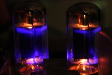
I'm not sure about the condition of the 3 remaining new tubes, though. First I had tubes in V9,10, and #10 would glow bluish when played with some (level 5-6) volume, while #9 was just orange. I swapped positions, and tubes and it seems that two tubes act identically, with blue coloration when played, while the last remained as described - just orange. Also the one tube was much less warm than the two that turned bluish. When I think of it, I think maybe the initial distortion went away with the cold tube out. Perhaps this last, cold tube is a little damaged...
Regardless the amp is doing quite well now, and I'm sure Twan will enjoy playing it again.
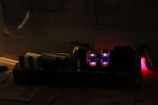
I added a couple af pictures, since I found the colors of the active tubes looks pretty nice - remember, this is a first for me
Just a final remark.
Junior came by tonight, so we hooked the amp up with speakers and a guitar and two tubes. It turns out that the amp is in pretty good shape - sound is good (some distortion in the beginning more clean after a little while), and volume seems decent at least it plays MUCH louder than on the previous test.
I'm not sure about the condition of the 3 remaining new tubes, though. First I had tubes in V9,10, and #10 would glow bluish when played with some (level 5-6) volume, while #9 was just orange. I swapped positions, and tubes and it seems that two tubes act identically, with blue coloration when played, while the last remained as described - just orange. Also the one tube was much less warm than the two that turned bluish. When I think of it, I think maybe the initial distortion went away with the cold tube out. Perhaps this last, cold tube is a little damaged...
Regardless the amp is doing quite well now, and I'm sure Twan will enjoy playing it again.
I added a couple af pictures, since I found the colors of the active tubes looks pretty nice - remember, this is a first for me
Attachments
Maybe a little late but place a 1R 2W resistor between the cathode and ground of each output valve cathode. This is where you can measure the bias current of each valve. Look for equal voltage across each resistor. See below;
The maximum output from an EL34/6L6GCW is about 25 watts, (KT88 about 65W). So measure the anode voltage of the amp, for this exercise we will assume that to be 445 volts. Divide the 25 by the 445 then multiply by 0.7 the answer in ma. is the 70% plate load bias setting required for that amplifier.
The 0.7 means 70% Hot anode / plate dissipation. Therefore you can use 0.5 (50%) as a Cool AB setting, 0.6 (60%) as a Warmer AB setting the one I would prefer. Or go for the 0.7 or even 0.75 (70 - 75%) if you like it hot.
Example: 25 / 445 X 0.7 = 39.3 ma. Bias or 39mV across cathode resistor.
The bias figure will depend on the anode voltage which will vary according to the current drawn by the valve. More current less volts, less current more volts. So you may need to do the calculation several times if large adjustments are made.
Example 2. 25 / 480 X 0.7 = 36.4 ma. Bias
Example 3. 25 / 410 X 0.7 = 42.6 ma. Bias
If looking for the Class A requirement, that's 100% plate dissipation. The figure to multiply by would be 1 but check the valve is operating within recommended plate voltages. Here is an EL34 example with 300 volts on the plate / anode.
25 watts max o/p of the valve divide by plate volts 300 multiply by 1 = bias current requirement for class A operation. Example. 25 / 300 X 1 = 0.083 = 83ma. or 25 / 350 X 1 = 0.071 = 71ma.
No rocket science - dead easy elementary stuff.
Maybe a little late but place a 1R 2W resistor between the cathode and ground of each output valve cathode. This is where you can measure the bias current of each valve. Look for equal voltage across each resistor. See below;
The maximum output from an EL34/6L6GCW is about 25 watts, (KT88 about 65W). So measure the anode voltage of the amp, for this exercise we will assume that to be 445 volts. Divide the 25 by the 445 then multiply by 0.7 the answer in ma. is the 70% plate load bias setting required for that amplifier.
The 0.7 means 70% Hot anode / plate dissipation. Therefore you can use 0.5 (50%) as a Cool AB setting, 0.6 (60%) as a Warmer AB setting the one I would prefer. Or go for the 0.7 or even 0.75 (70 - 75%) if you like it hot.
Example: 25 / 445 X 0.7 = 39.3 ma. Bias or 39mV across cathode resistor.
The bias figure will depend on the anode voltage which will vary according to the current drawn by the valve. More current less volts, less current more volts. So you may need to do the calculation several times if large adjustments are made.
Example 2. 25 / 480 X 0.7 = 36.4 ma. Bias
Example 3. 25 / 410 X 0.7 = 42.6 ma. Bias
If looking for the Class A requirement, that's 100% plate dissipation. The figure to multiply by would be 1 but check the valve is operating within recommended plate voltages. Here is an EL34 example with 300 volts on the plate / anode.
25 watts max o/p of the valve divide by plate volts 300 multiply by 1 = bias current requirement for class A operation. Example. 25 / 300 X 1 = 0.083 = 83ma. or 25 / 350 X 1 = 0.071 = 71ma.
No rocket science - dead easy elementary stuff.
Thanks, Jon. Yes a little late, but very well explained and if I ever get my hands on an amp like this again I'll know how to deal with bias.
In my case with this Fender the cathode would be pin# 8 and the anode pin# 3, I believe. This amp has a jumper from pin #8 soldered to ground, so the 1 Ohm resistor would replace this jumper in your setup?
The tubes should be in V7 and V10 or V8 and V9 not V9 and V10.. The way you have it now is wrong .
Ooops
Twan picked up yesterday, I'll let him know about the proper placement!
It plays quite well with tubes in the wrong sockets, though, but maybe even better with them placed correctly.
Has Twan noticed a difference when switching the tubes? You should notice a difference with them in the correct positions.
good luck guys
Hi 'bird
He says that he has placed the tubes in V8,9, and that he can't hear any difference. It may not be as loud as it was 10 years ago, he says, but then again he's probably not taking into account, that he's only using 2 tubes.
Thanks for asking - you saved this baby
- Status
- This old topic is closed. If you want to reopen this topic, contact a moderator using the "Report Post" button.
- Home
- Live Sound
- Instruments and Amps
- Fender PA100 - smoke -> no sound