An interesting point from Dennis on OTLAsylum is the WIMA caps (being stacked plates) are sensitive in how they're connected with the 4pin WIMAs being superior to the 2pin (he went a little further and suggested using a piece of silver wire between them and connect them at the centre point of that wire).
I've bumped into the 4 pins before on the SMPS power supply investigated previously. However Dennis is in a different league to my little build (IIRC that's Dennis Had). So for V1 it's a bit of a mish mash of what I have at hand, later if I want to try switching out the 2pins I'm using then I can do so.
I also remembered I hate thin PVC wire. Any side pressure causes the hot core to cheese wire through it. The thicker solid copper is ok but I would be concerned with the 320V stuff in this situation. So it looks like I'll be ordering myself some PTFE wire after all.
Last edited:
Noise floor.
I've been slow with the project again but I'm getting there and I'm starting to feel happy about the numbers for the specifications.
The ltspice modelling of the 9H 300mA choked power supplies (no regulator) shows a noise floor of 1.6mV, now this seems to be around -77dbV. I have about 20-25V of headroom that I'm currently using resistors in RC networks to reduce for the initial build.
Anyone thinking of bipolar powered tube amp.. be mindful of the power supply! I will have four power transformers, four rectifiers, 6 chokes (although I may have to look at going up in core size which would give me 500mA and only require 4 chokes thus be more cost efficient), a heap of caps..
The secondaries will be isolated independent so they will be future proofed for regulators at a later date.
I find it interesting, as an observation, that a lot of the tube amps don't use bipolar supplies but use centre tapped, or virtual grounds without rectification.. I can see why - the power supply becomes complex and costly quickly.
Looking at the result of ~10H is probably the reason why Stephe's current amp uses two 5H in series.
Quiet and slow..
I’ve been studying circlotrons. Musing low output impedance and current delivery.
A pp stage in a flutterman variant with 4 pairs of ecc99 would see a Zout of (Rp/4)/(2(1+u). Which with the ecc99 having an Rp of 2.3kohm and mu of 22 results in a Zout of 12.5ohm.
Although the Rp of a 6as7 is 280, it’s mu is low at ~2 so paralleling tubes gives 70 / (2+4) or appropriate Zout of 10ohm so quite close.
I found a couple of circlotron formulae, one says Zout = RP/(2+U) thus with our parallel tubes that’s 2300/(8+4*22) = 24 ohms.
Ralph (atmasphere) is on record stating Zout = 2Rp / (u+2) that has matched measurements within 10% so paralleled again in an m60 style would give Zout = 48ohms.
Given a cathode follower is Rp/(1+u).
What is interesting is that typically for a cathode follow differential stage you may want to tackle ground PSRR. Todo this the stages are cross-crossed allowing CMRR.
However a circlotron is a pair of cross-crossed cathode followers with the cap replaced by floating power supplies. Hmmm…
Also about the only real way to drop Zout is parallel the CF to increase mA/V that the stage delivers but reduce resistance. One comment is that negative feedback doesn’t reduce Zout - it merely corrects the input voltage swing thus reduces the resistance (mA/V increases) to match.
Therefore.. if you want Zout low impedance OTL .. the reality is either:
* 8+ tube sections…
* add a autotransformer with a 600 to low imp tap
* add and an air wound transformer (zOTL) that operates at RF.
* add SS cathode followers or replace the output section.
* ignore the zout damping of bass completely..
I’m considering switching to a hybrid circlotron.
Now in terms of hybrid, I favour tube with help rather than tube drives a hybrid stage.
This also fits the holes I’ve already made in the chassis")
This akin to the Broskie Brazilian OTL that has each SS following the cathode output. Resulting in low output Zout but enough power for speakers too.
What is clear is that the Brazilian otl is not a million miles away from a circlotron (grounding)
Lastly the question is: can ground PSRR be solved by adding CCS top and bottom (referencing ground) without destroying the floating nature of the circlotron?
I’ve been studying circlotrons. Musing low output impedance and current delivery.
A pp stage in a flutterman variant with 4 pairs of ecc99 would see a Zout of (Rp/4)/(2(1+u). Which with the ecc99 having an Rp of 2.3kohm and mu of 22 results in a Zout of 12.5ohm.
Although the Rp of a 6as7 is 280, it’s mu is low at ~2 so paralleling tubes gives 70 / (2+4) or appropriate Zout of 10ohm so quite close.
I found a couple of circlotron formulae, one says Zout = RP/(2+U) thus with our parallel tubes that’s 2300/(8+4*22) = 24 ohms.
Ralph (atmasphere) is on record stating Zout = 2Rp / (u+2) that has matched measurements within 10% so paralleled again in an m60 style would give Zout = 48ohms.
Given a cathode follower is Rp/(1+u).
What is interesting is that typically for a cathode follow differential stage you may want to tackle ground PSRR. Todo this the stages are cross-crossed allowing CMRR.
However a circlotron is a pair of cross-crossed cathode followers with the cap replaced by floating power supplies. Hmmm…
Also about the only real way to drop Zout is parallel the CF to increase mA/V that the stage delivers but reduce resistance. One comment is that negative feedback doesn’t reduce Zout - it merely corrects the input voltage swing thus reduces the resistance (mA/V increases) to match.
Therefore.. if you want Zout low impedance OTL .. the reality is either:
* 8+ tube sections…
* add a autotransformer with a 600 to low imp tap
* add and an air wound transformer (zOTL) that operates at RF.
* add SS cathode followers or replace the output section.
* ignore the zout damping of bass completely..
I’m considering switching to a hybrid circlotron.
Now in terms of hybrid, I favour tube with help rather than tube drives a hybrid stage.
This also fits the holes I’ve already made in the chassis
This akin to the Broskie Brazilian OTL that has each SS following the cathode output. Resulting in low output Zout but enough power for speakers too.
What is clear is that the Brazilian otl is not a million miles away from a circlotron (grounding)
Lastly the question is: can ground PSRR be solved by adding CCS top and bottom (referencing ground) without destroying the floating nature of the circlotron?
Just been doing some paper calculations for a hybrid circlotron output stage.
With a MJW18020G BJT as cathode follower to each ecc99 section, configured as 1:10 mA the max current jumps to 2.64 amps. However the Zout then drops from tens of ohms to 0.061 ohms.
Things get a little scary if you have a 200V supply circlotron and if a flashover occurs in a tube, the BJT would be happy to supply 10x the current. Closely followed by the circlotron attempting to rebalance.. but the DC would be (if the inductor trick works) would short to ground.
I want to model this all. However it looks good (possibly with caps isolating) and a global tripwire to disconnect/short to ground in this scenario.
A bit of a current monster with a 84 damping factor into 32ohms (conservative 1:10) and a barn storming 142 into 55ohm. A few modifications and it could drive 8ohm speakers.. but what is nice is that the tube output is used directly and the BJTs make up what is missing.
Last edited:

I’ve attached an abstract picture, there still plenty of resistors, diodes etx needed but shows what I’m thinking but there are some points I still need to think through:
* DC offset - Broskie has a LPF criss-cross that would work.
* driver section this could be set to bias the circlotron (m60 style) but I’m reluctant to remove the isolation between the floating power and the driver section. Some balance control would be good. The m60 uses B- but I have used ground (common mode noise injection) plus the use of -320 balance the psu at the cost of putting current through large resistances. Need to consider any benefit to -320 use here.
* driver feedback - this could drive in two ways - one to driver cathode/driver anode, or, the feedback goes back to the front end.
* heaters - the circlotron heaters should follow the floating supply.. but they could be placed on the +50V referenced heater supply if the circlotron doesn’t move too much. The 6sn7 will take more heater-Kathode abuse (and B+ limits are higher) than the 12bh7a and ecc99. Hence more complications.
* inductors - act as a passive constant current but in the even of arc-over the current would be horrendous so I need a way to simply short to ground (a TVS would work given the initial current surge would cause the inductor to create a voltage rise, but high current damaging an inductor… it needs a trap to simply short whilet disconnecting and collapse the power supply.
* isolating caps - it’s possible for the output caps I have to be used for headphone isolation. Caps will block DC but not an AC spike so an additional TVS voltage clamp is possibly needed.
Last edited:
Bridge within Bridge - Circlotron & VI Fontana Bridge
Right back home..
So, something that has been in the back of my mind is using a Fontana Bridge for impedance correction. I've also been playing with 0.32 ohm, and the BJT needs 9V VBE so this needs work..

Not modelled correctly but I'm looking at something like this - although I may switch the singe triode to a inverting differential amp rather than injecting direct to the grid.
I'll play with this a little more over the next few days but this is looking interesting as a concept.
It uses a flowing PSU circlotron which is a form of bridge, driving an inner fontana bridge to detect the difference in impedance, the output is (in a fontana) sent back through an error correction pair of opamps. In this version I will use two triodes todo the same - taking the output error correction and apply to the circulation bridge.
Right back home..
So, something that has been in the back of my mind is using a Fontana Bridge for impedance correction. I've also been playing with 0.32 ohm, and the BJT needs 9V VBE so this needs work..
Not modelled correctly but I'm looking at something like this - although I may switch the singe triode to a inverting differential amp rather than injecting direct to the grid.
I'll play with this a little more over the next few days but this is looking interesting as a concept.
It uses a flowing PSU circlotron which is a form of bridge, driving an inner fontana bridge to detect the difference in impedance, the output is (in a fontana) sent back through an error correction pair of opamps. In this version I will use two triodes todo the same - taking the output error correction and apply to the circulation bridge.


So the hybrid output stage is looking good - this is the first run, so some tuning is needed. Also some updates but it's looking good.
Basically it uses the four ecc99s to provide the output then uses a current mirror to provide additional current. The glassware is isolated by caps but the 40V hybrid section provides direct current.
The hybrid is made up of two class A circlotrons. I had tried simply adding BJTs within the same power circuit as the tubes, the issue then becomes attempting to bias both the tube and the BJTs in the same circuit. In short that works for Class AB or B but not for class A, the resulting load line idle point sits too close for the 450V 2A BJT to provide a full save form.
So instead for now I have used a 200V supply for the ecc99s and a 40V supply for the bits. The current mirror simply uses the first BJT to sense the current from the tube cathode output and then provides additional current from the second BJT.
I will look at possibly adding additional BJTs to reduce output impedance, but for now that will do. However the output BJT could be switched for 36V peak capable and, with a little tuning of gain, drive speakers with about 80W.
The bode plot with 1V AC shows:

Last edited:
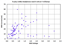
When I designed a headphone amp a couple years ago, I found this table (hosted on head-fi.org) to be indispensable:
Headphones: sensitivity, required voltage, required current, required power, impedance, gain
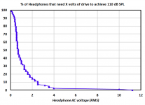
I slurped the numbers into an excel spreadsheet and plotted the cumulative distributions. These distribution graphs were quite helpful to me, I hope they are useful to you as well.
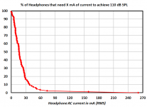
Hot take executive summary: if you want your headphone amp to be able to drive more than 90% of "all possible headphones" to 110dB SPL, design your amp to deliver at least 3V RMS and at least 40mA RMS. If your output stage is both single ended and Class-A, this means: run it at a bias current of at least 75mA DC ... and 125mA DC is even better.
_
Headphones: sensitivity, required voltage, required current, required power, impedance, gain
I slurped the numbers into an excel spreadsheet and plotted the cumulative distributions. These distribution graphs were quite helpful to me, I hope they are useful to you as well.
some members feel the plot titles are incomplete; these folks suggest that the red curve would be easier to interpret if its title were
% of Headphones that need X mA or more to achieve 110 dB SPL
% of Headphones that need X mA or more to achieve 110 dB SPL
Hot take executive summary: if you want your headphone amp to be able to drive more than 90% of "all possible headphones" to 110dB SPL, design your amp to deliver at least 3V RMS and at least 40mA RMS. If your output stage is both single ended and Class-A, this means: run it at a bias current of at least 75mA DC ... and 125mA DC is even better.
_
Attachments
Last edited:
Thank you Mark.
I have a quick chance to play with some of the parameters. A bias change on the output is putting 160mA peak to peak across 55ohms. It’s capable of more.
This was it’s first 30 mins, so I’ll read through that material. I’ve tuned town the front end gain deliberately to keep distortion low but also not overload the output stage input. I’ve been using 3.16*1.414 for input but it’s tuneable - my CD player Debra on the recording. Metallica pushes 1.5v peak.
As the design doesn't use a tube into SS to load but rather the tube output drives the SS current support is that the tubes see the headphone impedance and the current mirror then mirrors that behaviour. This is because the tube doesn't see a constant input impedance to the next stage in this design.
This is full scale input at 4.5V. The output is pushing 100mA peak in each direction into 55ohm.

You can see the effect of the tube vs impedance has. To counter this, I found that the capacitor I use for isolating the power loops in the current mirrors needs tuning to prevent the base rolloff.
This poses a problem. Given my HP's 55ohms is the lowest impedance but ASR have measured that the impedance goes up to 800ohm at at the top end.
Hmm need some thinking. The idea is that the BJTs could be swapped out and replaced with higher current to power speakers (or simply a switch between boards to switch between headphones and speaker out - using both would require the current loops being kept separate like the tube-SS loops are in this design).
I've temporarily corrected this by tuning the 14.5uF cap in the current mirrors. The issue I think is that the cap is then acting as a filter along with the BJT and impedance.

I need to look further into this.
Edit my hunch was right - the 10K and the 14.5uF cap was acting as a filter. Increasing the 10K to 1M has solved the issue.
This is full scale input at 4.5V. The output is pushing 100mA peak in each direction into 55ohm.
You can see the effect of the tube vs impedance has. To counter this, I found that the capacitor I use for isolating the power loops in the current mirrors needs tuning to prevent the base rolloff.
This poses a problem. Given my HP's 55ohms is the lowest impedance but ASR have measured that the impedance goes up to 800ohm at at the top end.
Hmm need some thinking. The idea is that the BJTs could be swapped out and replaced with higher current to power speakers (or simply a switch between boards to switch between headphones and speaker out - using both would require the current loops being kept separate like the tube-SS loops are in this design).
I've temporarily corrected this by tuning the 14.5uF cap in the current mirrors. The issue I think is that the cap is then acting as a filter along with the BJT and impedance.
I need to look further into this.
Edit my hunch was right - the 10K and the 14.5uF cap was acting as a filter. Increasing the 10K to 1M has solved the issue.
Last edited:
I've tuned this a little. Using a 2M and switching from a 14.5uF to a 0.022uF ! flattens the response at the load considerably
Lines here are for 32, 55, 64, 120, 300 and 600 ohm loads. The 600ohm is the top line near 9.7dB.

For kicks and giggles I've added both 4 and 8 ohm loads into the list:

I suspect the poor old BC547Bs would throw a tantrum attempting that. -6dB into 8ohms.. you'd hear it quietly!
Lines here are for 32, 55, 64, 120, 300 and 600 ohm loads. The 600ohm is the top line near 9.7dB.
For kicks and giggles I've added both 4 and 8 ohm loads into the list:
I suspect the poor old BC547Bs would throw a tantrum attempting that. -6dB into 8ohms.. you'd hear it quietly!
Last edited:
So starting to work out the final tuning.
The heavy third harmonic is simply this (and a common issue with cascodes) - the top cascode is sitting too close to the top the B+ and on amplification, so the peak of the waveform is clipped.


I made an adjustment to tune the Vpp down but I may simply use a voltage divider instead. There's not a lot of current at this stage.
There's also a more important secondary issue I need to sort out:

Blue - output voltage
Red - input into the NPN in the current mirror
Green - tube output voltage
The resulting blue wave form is misshapen due to the phase shift of the two input waves - both sets of waves go through caps to isolate. The green goes through a large bank of caps to isolate the tube and headphone. The blue is the after the isolation cap of the current mirror. It's not the current but the voltage.
So essentially the caps are not shifting the phase by the same degree. So I will need to work out how to correct this or the amp will be third harmonic heavy.
The heavy third harmonic is simply this (and a common issue with cascodes) - the top cascode is sitting too close to the top the B+ and on amplification, so the peak of the waveform is clipped.
I made an adjustment to tune the Vpp down but I may simply use a voltage divider instead. There's not a lot of current at this stage.
There's also a more important secondary issue I need to sort out:
Blue - output voltage
Red - input into the NPN in the current mirror
Green - tube output voltage
The resulting blue wave form is misshapen due to the phase shift of the two input waves - both sets of waves go through caps to isolate. The green goes through a large bank of caps to isolate the tube and headphone. The blue is the after the isolation cap of the current mirror. It's not the current but the voltage.
So essentially the caps are not shifting the phase by the same degree. So I will need to work out how to correct this or the amp will be third harmonic heavy.
Last edited:
Hi nick, I really like the name of your amp "c'est compliqué"
I have a hybrid to show you
simulation of a hybrid amp : so long
I have a hybrid to show you
simulation of a hybrid amp : so long
Hi nick, I really like the name of your amp "c'est compliqué"
I have a hybrid to show you
simulation of a hybrid amp : so long
Nice! (The wife is French)
I see the link has a final mosfet output stage. I think I made it doubly difficult by attempting to keep the tube output then augment it with a current drive whilst isolating two differing power loops.
There's also a more important secondary issue I need to sort out:
So essentially the caps are not shifting the phase by the same degree. So I will need to work out how to correct this or the amp will be third harmonic heavy.
A quick model on the smaller model with a duplicate set of caps has corrected the issue.
Only issue here is that each mirror 'cap' is now a cap bank of 4x330uF and a 0.22uF to mirror the phase shift. For a tube OTL this amount of output capacitance prevents rolloff and allows current (the paralleled caps means less ESR too). In fact in the previous totem PP design, each opposing pair of tubes had a cap bank.
In the hybrid there's no getting away from this either as the mirror isolation should not roll off any low frequencies.
Let me make the modification and let the big sim run. Hmm with paralleled tubes comes the fun of varying parallel capacitance which then could cause a variable phase shift like a varistor.
First wave (hence misshaped) of the model shows they're in phase:

Will allow the model to run for 10 sim seconds..
Last edited:
So I spent yesterday evening going back over the cascode.
I'm aware that LTSpice gives a rough simulation vs real results however as DF96 used to say it points to problems and cascodes seem to be problematical.
Current tuning - this is with the tube CCS at the bottom replaced by a resistor and a 1.5V balanced input.

And using one side of the amp output:

At some point I will work out how to trick LTspice into FFTing a difference rather than only FFTing the node points.
I'm aware that LTSpice gives a rough simulation vs real results however as DF96 used to say it points to problems and cascodes seem to be problematical.
Current tuning - this is with the tube CCS at the bottom replaced by a resistor and a 1.5V balanced input.
And using one side of the amp output:
At some point I will work out how to trick LTspice into FFTing a difference rather than only FFTing the node points.
Last edited:
If I do this old school with the load lines it looks like the 12BH7As are struggling with the 320V and running lower in their voltage range.. if there's anything that tubes like is voltage.
So I've increased the rail voltages to 365V. I'll need to check the cathode heater voltages later but for now I want to see/describe the approach I've taken.
First. I want to run a tube CCS so that, if I'm running a single section, limits me to 20mA max and preferably 18mA total through both of the differential sections.
12BH7A-STR datasheet attached.
First I've put in a resistor rather than the CCS - we can add that back in later. -360V means it now has a lot of room down there.
From my understanding a cascode is a transconductance amp cascading into a transimpedance amp.
The input tube is a transconductance (converting voltage to current).
The 'cascode' tube with it's common grid then 'amplifies' the current by changing the resistance. My understanding this is a transimpedance - (converting current to voltage) and hence with Ra you then have an output voltage.
The next stage in the amp is a cathode follower - this, through a cap and 1M grid leak, presents a high impedance to the high impedance output of the cascode.
So in my head I take the input tube as a normal triode, although it's limited to a 9mA bias. The kicker here is - what is the Ra that the input tube sees as this defines the load line?
Well I look at this as 9mA through the input tube, then I have the same 9mA idle that needs to go through the cascode as a operating Q point. This means that both tubes should really run with a voltage across the tube to handle the current. The lower tube sets the voltage bias point so you're simply adding to that.
So you know the bias point, the required idle current and so you're then free to choose the upper voltage and Ra. Within reason.. the tube needs room to breath in voltage, this means the rail voltage increases (hence why SS folded cascodes are popular).
Input triode
Input range is 3.16*1.414 ie 4.5V but the reality here is to run with a cathode bias of 6-7V. The data sheet suggests -10.5V and 11mA. Instead to run a Iq of 9mA and a 6-7V cathode bias means our Q point is about 175V.
This means the differential pair is drawing an idle current of 18mA.
I'm positioning the triode to be able to take a direct input through a 4.79K resistor. There's no DC blocking cap in the way.
Also my GNFB would also feed into this (I could feed into the drivers but for now I'm running without NFB.
Cascode triode
Now we know the voltage across our input should be 175V, I've added 6.7V to that to give 182V. which is now the target for the top of the input triode. I can set that by using two diodes in series of 150V+30V. In the sim this results at about 186V. Near enough.
What I'm doing here (rightly or wrongly) is attempting to match the current at idle so the input and cascode are running at 9mA. The final output of the cascode will obviously depend on Ra above the cascode tube.
Next I add 186V+175V to give 361V. Now the Ra of 500ohm means 0.009*500 = 4.5V drop, so 361+4.5 = 365.5.. so hence the 360V rail.
The resulting output is 4Vpp with an 1.5Vp input.
Driver triode cathode follower
The driver triode is more like a buffer, presenting a high input impedance but low output impedance to provide current drive into the paralleled tube sections.
The standard M60 uses drivers to direct connect and bias to the output cyclotron pairs. My design is slightly different that uses a 1uF+0.22uF cap to provide enough drive to the four parallel grids.
This also has the benefit of being able to use the full 20mA range plus it's connected rail to inject noise from both rails. The downside of this technique is that it now has a large resistor in the 20mA max flow.. which is looking at 3W so parallel resistors to reduce to 1.5W would be needed to stop the thermal noise levels increasing.
The H3 sim output is annoying, however from others - this is often less evident in the real amp.
Attachments
Last edited:


So the tuned cascode front end is giving me 33dB of gain from 22 mu tubes without negative feedback.

It's not as flat as my previous tuning, however this presents the harmonic spread shown before above.
The driver stage is attenuating - this has a potential divider (3Meg and 1Meg) on the grid to keep within the respectable grid parameters:

The grids of the output ec99s see a little bottom end roll off:

However this is first view of the problem that causes the large phase shifts when feedback is used:

Green - the grid as before, the yellow shows the cathode of one of the triodes, and the red shows the respective load connection.
When NFB is used this amplifies this shift cause it to repeatedly shift the signal on each loop.
So as phase shift and group delay shift is related to resistance and capacitance configurations, I know the characteristics but not the location. I do know that changing the caps in the tube output changes this but the next diagnostic check is the solid state interaction with the caps.
It's not as flat as my previous tuning, however this presents the harmonic spread shown before above.
The driver stage is attenuating - this has a potential divider (3Meg and 1Meg) on the grid to keep within the respectable grid parameters:
The grids of the output ec99s see a little bottom end roll off:
However this is first view of the problem that causes the large phase shifts when feedback is used:
Green - the grid as before, the yellow shows the cathode of one of the triodes, and the red shows the respective load connection.
When NFB is used this amplifies this shift cause it to repeatedly shift the signal on each loop.
So as phase shift and group delay shift is related to resistance and capacitance configurations, I know the characteristics but not the location. I do know that changing the caps in the tube output changes this but the next diagnostic check is the solid state interaction with the caps.
- Home
- Amplifiers
- Headphone Systems
- Designing my headphone amp