Those actually look real. The legs on real Toshiba have kind of a rough tinning. The way to tell also is the font and lettering and how neat the edges of the epoxy package are. The lettering should be printed not laser etched. You have to compare to a genuine. I have bags of the genuines from Mouser before they sold out.
Grimberg posted source for remakes of the 2SA1837.
Toshiba 2SA1837, are these good?
That looks good too.
Grimberg posted source for remakes of the 2SA1837.
Toshiba 2SA1837, are these good?
That looks good too.
Well that makes me feel better about the 2SA1837 I have. The legs do look like they were tinned, I just didn't imagine they came that way from the factory. Lettering is not laser etched, more like it was printed with a die.Those actually look real. The legs on real Toshiba have kind of a rough tinning. The way to tell also is the font and lettering and how neat the edges of the epoxy package are. The lettering should be printed not laser etched. You have to compare to a genuine. I have bags of the genuines from Mouser before they sold out.
Grimberg posted source for remakes of the 2SA1837.
Toshiba 2SA1837, are these good?
That looks good too.
So could I use 33k for R11 for 6db of gain? That would probably do it for me.
I took another careful look at my genuine 2SA1837's - and I have two batches. One Aksa, who said he got them from the Toshiba factory 10 years ago, and one from an order I placed to Mouser 2 years ago. They may actually be laser etched - but finely done and deep. Not lightly done as on some knock offs. There are a few details like bevels on the epoxy and a small copper circle visible at the bottom of the lower two divets on the front tab. The legs are the biggest giveaway though. New knock offs will not be tinned but shiny plated stamped die-cut metal (maybe not even copper). Genuine will be tinned with Pb solder (before the who Pb free era) smoothly done over partially exposed copper legs.
Here are some photos of front and backside:
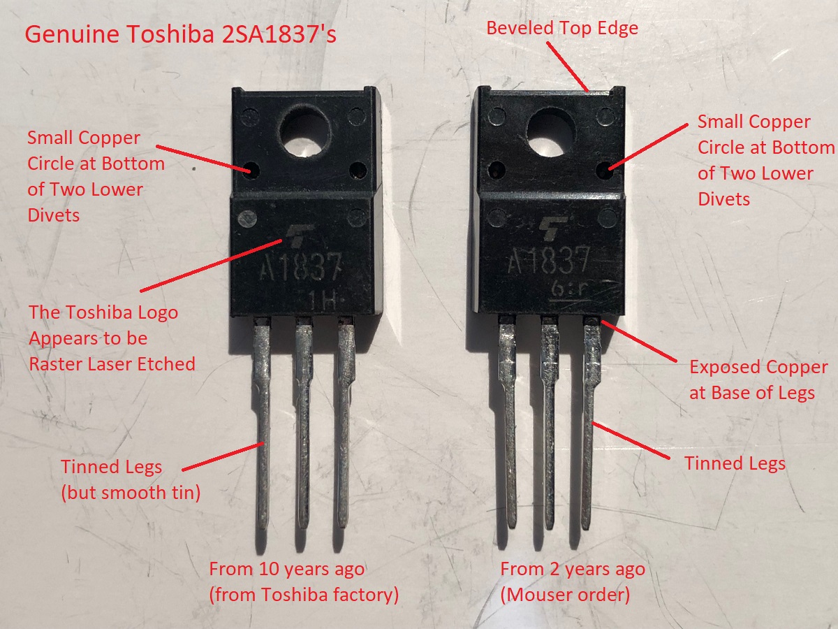
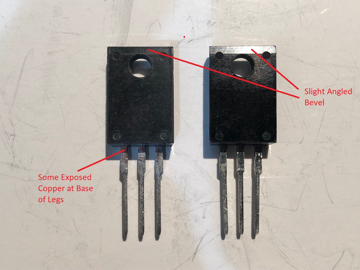
Looking at your photo your 2SA1837's, I see the copper in the divets, the bevel on the case, and the tinned legs - I believe you have genuines.
Here are some photos of front and backside:
Looking at your photo your 2SA1837's, I see the copper in the divets, the bevel on the case, and the tinned legs - I believe you have genuines.
Attachments
Last edited:
....
Looking at your photo your 2SA1837's, I see the copper in the divets, the bevel on the case, and the tinned legs - I believe you have genuines.
Fantastic! Thanks for the detailed compare. Moving ahead I ordered the following.from Mouser
R10 - 33k KOA Speer Carbon Film
R11 - 15k Vishay Metal Film
R15 - 22R Vishay Metal Film
Purchased 4 of the 22R to parallel for 11R. Also verified that I have 2.2R for R14. Hopefully I got it right. Full speed ahead with this build.
A couple of the resistors are specked as carbon in the BOM, R113 and R10.
For R113 I have a 10k 1/2W 5% Yageo CFR-50JR-52-10K
For R10 I have a 33k 1/4W 2% KOA Speer CFS1/4CT52R333G.
All the metal film resistors are 1%. I thought I read in one of the AKSA Lender threads but can now not seem to find it that you can use carbon but may need to check them since the tolerances are not as close. Is there anything I should test before installing these?
Also I have the TH boards, am I right in thinking that R113 belongs on the SM board and is part of the TH BOM by mistake? If so could I use one of the 10k 5% resistors for R141? Somehow I missed the change when ordering and did not get it.
Last edited:
Yes, sorry - no R113 or R13 to be found on TH board anywhere. The CF resistors you picked look fine.
Fortunate mistake for me since if it wasn't for that I would need to order one
")
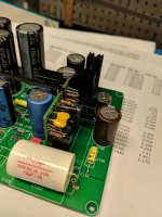
Yes, if you look at the board, the pads for the heatsink are connected to the ground plane. You will have a short of your PSU to ground if you don’t use a insulating silicone pad and plastic shoulder washer.
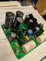
Thanks, anything to worry about with the small heatsinks off the daughter card? They look to be only connected to the transitors which are fully encased but this is all new to me.
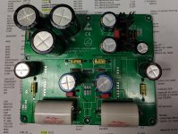
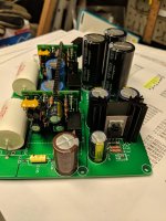
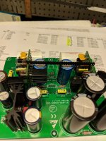
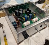
Had to bend some stuff around plus solder the connectors on different sides between the DBs to get everything to fit. Hopefully the heatsinks have enough clearance to live happily.
Soldering up the DBs was a lesson in solder control plus the size was about the limit for my vision. Also think I should get a smaller tip for next time.
Soldering up the DBs was a lesson in solder control plus the size was about the limit for my vision. Also think I should get a smaller tip for next time.
Attachments
Is this how I should wire the inputs and outputs? Goal is to select between 3 inputs and have 2 RCA outputs plus a headphone jack. Only one set of RCA outputs will switched off when the headphones are plugged in. I have a break before make switch Elma 01-1264 and Alps 10KAX2 pot. Was not planning to use the selector pcb or mount the pot on the pcb.
Attachments
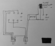
Is this how I should wire the inputs and outputs? Goal is to select between 3 inputs and have 2 RCA outputs plus a headphone jack. Only one set of RCA outputs will switched off when the headphones are plugged in. I have a break before make switch Elma 01-1264 and Alps 10KAX2 pot. Was not planning to use the selector pcb or mount the pot on the pcb.
Or would it be better to use the selector pcb and just run wires to the inputs, selector switch and outputs from it and then use the ribbon cable to connect to the MB?
A new HPA based on Aksa Lender topology bit worh dual rail PSU and DC coupled output as option.
The YARRA Preamplifier/HPA for Melbourne DB Group Buy
The YARRA Preamplifier/HPA for Melbourne DB Group Buy
- Status
- This old topic is closed. If you want to reopen this topic, contact a moderator using the "Report Post" button.
- Home
- Amplifiers
- Headphone Systems
- Aksa Lender HPA