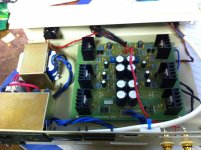
I followed these steps and wow what a difference, its still very sensitive to interference on the cabling but with careful adjustment of cable routing there is almost no background hiss at full amplification, I do notice some crackle when adjusting the volume; but I am certainly impressed. ")
Thanks to all for the suggestions
Thanks to all for the suggestions
Lets try to fix your issues.
The ferrites will not solve your problem. You should remove them because they add no value in your situation - your problems are elsewhere as outlined below.
1. It looks like you are using non screened wiring to connect your volume control to the circuit board. I'd use some screened wire here - so inner two wires would be signal, and the screen the ground side of the pot. Reason: the pot wiper is a high source resistance, and therefore susceptable to a lot of noise pick-up via capacitive coupling.
2. You potentiomenter housing should have a good connection to ground - this should happen in any event because of the way the pot is mounted on the front panel. However, double check that your potentiometer shaft to chassis is open circuit. Highly unlikely, but just check it anyway.The pot housing acts as a screen, and prevents capacitive coupling onto the pot track.
3. Your cabling from the transformer onto the PCB - twist the wires tightly together so you minimize the area between the wires - this will reduce radiated noise (50/60Hz and harmonics). The way it s hooked up now means all this gunk is coupling into the volume pot wires and the PCB tracks.
4. Your headphone socket. Same story, twist the ground and L and R channels wires tightly together. Keep this bunch of cables well away from your pot cables and the transformer cables.
5. Use a meter and check carefull that your headphone socket is NOT electrically connected to the chassis other than via the headphone ground return wire to the PCB. To do this, unsolder the wires to the headphone socket and measure the socket ground to chassis - it should be open circuit. If you have a short, or low Ohms reading, you have a ground loop, and this will give you noise and hum.
6. Check that your input sockets are not connected to the chassis other than via the screen on the socket to PCB wiring.
7. You must have only 1 connection from your circuit board to the chassis. This must run from the junction of the filter capacitors to a secure point on the chassis. The incomming earth from the AC line receptacle must also be connected to the chassis. If there is any other path to the chassis other than via the single wire from the junction of the filter capacitors, it willl create an earth loop, and you will get hum and noise. Further, if you are anywhere near a PC or SMPS adaptor powered devices, the radiated noise from that adaptor wilol couple into your amplifier causing hum, hash and a lot of HF noise. Terrible stuff.
8. Final points: Keep the potentiometer wiring well way from the headphone and transformer wires. Keep the transformer wiring well away from the headphone and potentiomer wiring. Twist the wiring tightly as mentioned above.
Follow these simple rules and its quite easy to build audio stuff that is as quiet as good commercial equipment - so down at -100 to -120dB.
Lets tackle the problem you have when you plug into your PC after you have sorted the above problems out - I suspect however if you do 1-8 above, your problem will be solved.
Attachments
"The DC offset at the output varies by as much as 0.1v, and is entirely temperature dependant. The only safe way to keep using this amp is to build a DC servo, which got the DC offset down below 1mV "
Sorry to bother but vhat about building case vith fan thats heave indipendent power suply of course and use it to keep JHL cool????
Just a toot of non electronocal mind..... ?
"Sorry to bother but vhat about building case vith fan thats heave indipendent power suply of course and use it to keep JHL cool????
Just a toot of non electronocal mind.....
?DC Offset
Before you add a DC servo or a fan, suggest you try putting all power devices on a common heat sink with a thick aluminium backing plate first.
Something like this :
http://www.diyaudio.com/forums/pass-labs/121228-f5-power-amplifier-24.html#post1538832
Patrick
Before you add a DC servo or a fan, suggest you try putting all power devices on a common heat sink with a thick aluminium backing plate first.
Something like this :
http://www.diyaudio.com/forums/pass-labs/121228-f5-power-amplifier-24.html#post1538832
Patrick
Last edited:
heliguy.
great to hear you have made progress!
With respect to the crackle when adjusting the volume, there are three causes that spring to mind:-
1. If the input is direct coupled from the pot wiper into the amplifier (i.e. no input capacitor), then the input stage bias current flowing through the pot track and into the wiper causes a crackling noise only as you rotate the pot. Only way to fix this is to AC couple the pot into to your amp. Note that the higher the pot value the worse the problem. And, the higher the amplifer input bias current, the worse the problem too.
2. The second possible cause of this problem is a little more insiduous. If your amplifer is oscillating, you can get the same cracking sound as the oscillation is coupled into the potentiometer, and then rectified by the input devices. What you may notice with this type of problem is that the output is quiet, then as you rotate the pot a bit more you get cracking and noise, and then quiet again and so on.
3. The third one is when there is a high frequency, high level noise signal being picked up by the input wiring before the pot. You get a similar effect to that described in (2) above, as the noise is rectified by the input devices.
Do you have a circuit diagram?
Also, you did not mention anything about the hum - has it now disappeared?
I just completed wiring everything to this JHL amp from e-bay. Initially hum was heard when touching the volume pot, I soldered a wire from the pot metal chassis to ground and problem solved.
I also encountered the DC offset at the output and it does goes crazy with temperature variation.
I added 470uF caps at the output and problem solved. I did listened to the sound quality with and without the output caps, but couldn’t discern any difference.
IMHO the DC servo circuitry is ok for the learning experience, but it is not absolutely necessary.
This amp is really a steal, the sound quality is fantastic and it cost me less than 50US to build including power transformer plastic box, jacks, wires,etc…
Hi All
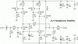
Well JLH Headphone Fans
Here is a Headphone version of the JLH single ended Class A speaker Amp that you all maybe interested in I am collecting the parts so haven’t build it as yet
Hi,
where did you get this schematics from? Have you already built it? What are the potentiometers VR1 and VR2 for and how should they be properly set up? I was planning to build original fig.1 schematics, so I suppose this one is better?
Can I use BD139 for the output transistors?
Thanks.
Attachments
JLH class a headphone amplifier
Hi
I installed the remote control option, as you can use the headphone amp as a active or passive preamp as well.
i use the JLH headphone amp as a active pre amp feeding a pair of velleman k8011 mono block valve amplifiers
regards
Jamesfeline
Hi
I installed the remote control option, as you can use the headphone amp as a active or passive preamp as well.
i use the JLH headphone amp as a active pre amp feeding a pair of velleman k8011 mono block valve amplifiers
regards
Jamesfeline
Hi,
where did you get this schematics from? Have you already built it? What are the potentiometers VR1 and VR2 for and how should they be properly set up? I was planning to build original fig.1 schematics, so I suppose this one is better?
Can I use BD139 for the output transistors?
Thanks.
Hi
This Schematic came from Geoff of the Class Amps site he is the man you want I haven’t built it just getting the parts together V1/V2 Are for setting up the Idle Current and DC off Set this link will take you to his site and the speaker amp version email him he is very nice chap he will help you
The Class-A Amplifier Site - JLH Class-A Update
Must agree, the amp sounds great but is impossible to use in any practicable way. Can you update us did the servo circuit solve this problem over the long term. I have ordered the caps for the output as suggested by another poster and will try them, but I would like to try the servo circuit next is it possible you might post an idiots guide to building and integration? I don't know much about electronics but I can do what I'm told.A quick followup on that kit
The DC offset at the output varies by as much as 0.1v, and is entirely temperature dependant. The only safe way to keep using this amp is to build a DC servo, which got the DC offset down below 1mV
For more details, see here:
Rock Grotto Audio Forum - For Headphones - Headphone Amps - Amplifiers - X-Can V2 - Musical Fidelity - headphone Discussion - Amplifier Discussion - DIY - Amplifier Kits - Projects - SCHA - Sennheiser - Beyer - Grado - Audio Technica - Headphone amp
Great sounding amp, using it as my main amp now
wEWk~$(KGrHqEOKj0EyLWK55U)BMj8dgVVZ!~~_12.JPG)
I have built JHL headphone according to attached schematics. I have regulated rails and have absolutely no problem with offset, max +-10mV.
Your posted picture looks like turn-on delay to mute the output during powering up. Mine headphone amp makes some small pop sounds during powering on and off, but nothing to worry about.
So is your problem related to unstable dc output offset or turn on pop?
Your posted picture looks like turn-on delay to mute the output during powering up. Mine headphone amp makes some small pop sounds during powering on and off, but nothing to worry about.
So is your problem related to unstable dc output offset or turn on pop?
Attachments

Member
Joined 2009
Paid Member
The only safe way to keep using this amp is to build a DC servo
In the spirit of the simple discrete JLH style amplifier I made up a single ended, single BJT dc servo for use on an amplifier with similar current feedback topology.
If it's of interest.... http://www.diyaudio.com/forums/solid-state/167369-designing-tgm3-output-triples-7.html#post2469136
p.s. for those who want to use this, it's not ideal for eliminating the feedback shunt capacitor as this increases chance of turn-on-thump. To eliminate this capacitor you need a push-pull dc servo.
Thank you very much sir,
I've found this some time ago :
Rock Grotto Audio Forum - For Headphones - Headphone Amps - Amplifiers - X-Can V2 - Musical Fidelity - headphone Discussion - Amplifier Discussion - DIY - Amplifier Kits - Projects - SCHA - Sennheiser - Beyer - Grado - Audio Technica - Headphone amp
is it same solution ?
(sorry my knowledge about diy is very low; a friend of mine is building this for me)
I am just sound engineer..
thanks
Member
Joined 2009
Paid Member
No, it's not a dc-servo solution. I uses two diodes as part of the biassing for the input transistor - the idea being that these diodes will vary with temperature and shift the input operating point to compensate for the effect of temperature on other devices in the amplifier with the end result that it will help maintain a stable dc-offset. This can work, I tried it initially in my TGM3, but I didn't use enough diodes to compensate for the changes. If the version in the link you sent is already built by others and known to work, then I would suggest it's a good choice as well as being simpler than the servo I implemented.
Hi all,
A few days back I also build this headphone amp. I looked for version with multiturn bias control. Bias starts at ca .5V but drops to ca 50mv in a couple of seconds. After a minute it's stable at +/- 10mV, which is fine by me.
I bypassed the 7x12 regulators and used a regulated PSU instead.
I had some trouble finding the correct value for the input DC coupling capacitor. C13 in the scheme below:
http://dl.dropbox.com/u/11569460/JLH Amp Scheme.png
They provided 300pF polymer, but there was totally no bass with that setting. I replaced with 82nF MKT which sounded fine. On the PCB 105 is listed as value (0.1uF?), the scheme tells me to use 1uF (which won't fit in polymer form) The seller advised me to use 0.47uF. I tried 0.47uF WIMA MKS, but that sounded a bit muddy. So I sticked with the 82nF MKTs.
The AMP sounded perfect on my AKG K501 (the best I even had in combination with that headphone) but very dark with my Sennheiser HD650. Way too much low-mid. Then I noticed that the Sennheiser sounded perfect when I kept some distance between the cushions and my head (thus removed the seal the headphone makes with my head). I do not need to do that with other headphone amps I have.
Any comments on why it sounds neutral with my AKG and muddy with my Sennheiser?
Hi
I'm new to the forum and glad to have joined at least one good one for my music interest.
I'm actually a Producer and have worked in Radio station Production studio's making radio station adverts.I have been dj'ing and producing for around 18 years on and off so I'm always on the quest for better sound.
Heliguy.....Hi.....I can also fly RC Helicopters although I'm not as good as others I have seen.....Anyhoo if you look on google there are Toroid Coils for about £10 rated 15Vx2...have you considered trying them? This is supposed to be an A-Class Headphone amp so I would naturally go for a Toroid rather than a H-Core XFormer?? Just a thought as I'm on the mission to buy one of these myself so I been doing a little research of my own and from years ago I know that A-Class Amplifiers use Toroids in them to supply a better RMS Voltage for a more constant AC Supply.
Does anyone remember the REAL Hybrid A-Class power amps that came out years ago....1000 and 1200Watters? They were in tough competition with the Linertech KW amps used for parties but hell did we go through speakers with them!! Funny thing about A-Class amps is that your speakers NEVER distort they just POP and thats the end of it.I laugh when people say speakers are distorting because it's not speakers that distort in the way they are saying it is the Amplifiers that cannot drive them so you get an influx of DC power coming through the amps "Distorting" the speakers. DAS. and Black Widows were the only speakers that could withstand the power of the old Hybrids and Linertechs.
One question...If I use just the Toroid transformer unregulated will it still work to drive this board??
Thanks
I've just ordered the parts for this project and I learned something new.I'm going to run mine with an audio grade toroid with low interference and high efficiency.It's a 30VA 2x15V rated 2A which gives me a total of 60W (Double) the recommended input which supposedly gives the headphones more headroom.This being much more efficient than one with a current output of 1A.
I figured if I'm going to build a nice little headphone amp, it's worth it to see how far I can push it and make it worth my while.Got a nice little box for it too.
I figured if I'm going to build a nice little headphone amp, it's worth it to see how far I can push it and make it worth my while.Got a nice little box for it too.
- Home
- Amplifiers
- Headphone Systems
- JLH Class A headphone amplifier