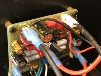
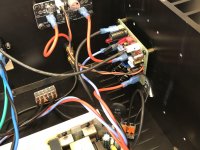
You seem to power the SSR from the amp board itself. Taking the + from near the resistor close to the positive power pin and the ground from the psu ground. Not visible from the dark pictures properly, can you please post some well lit pics and also let us know how did you power the SSR boards.
thanks
That's exactly how the SSR is powered - it just needs access to +ve rail voltage anywhere you can get it. Here, it is right at the 10R resistor. On the FH9HVX PCB, I will have a Molex KK 2pin connector dedicated for powering thge SSR, same as on the Alpha Nirvana. It just makes it a lot easier to connect the SSR.
@Manniraj,
I apologize for the dim pictures, I was trying to capture the lit LED’s.
You have good eyes! Yes, I tapped V+ off the 10R resistor leg, it was the easiest location without removing the board from the heatsink. The GND is picked up from the GND faston on one board and at the psu GND for the other board.
Like X said, adding the Molex 2-pin header will make this connection a simple plug’n’play")
@Meanie,
Hahaha!! Yes, as far as generated heat, this amp is certainly not like the space heaters we’ve been working on. Would be perfect for your HOT summers.
I apologize for the dim pictures, I was trying to capture the lit LED’s.
You have good eyes! Yes, I tapped V+ off the 10R resistor leg, it was the easiest location without removing the board from the heatsink. The GND is picked up from the GND faston on one board and at the psu GND for the other board.
Like X said, adding the Molex 2-pin header will make this connection a simple plug’n’play
@Meanie,
Hahaha!! Yes, as far as generated heat, this amp is certainly not like the space heaters we’ve been working on. Would be perfect for your HOT summers.
Attachments
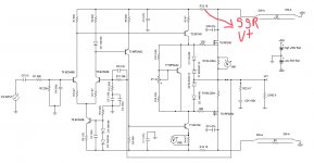
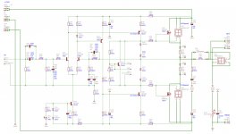
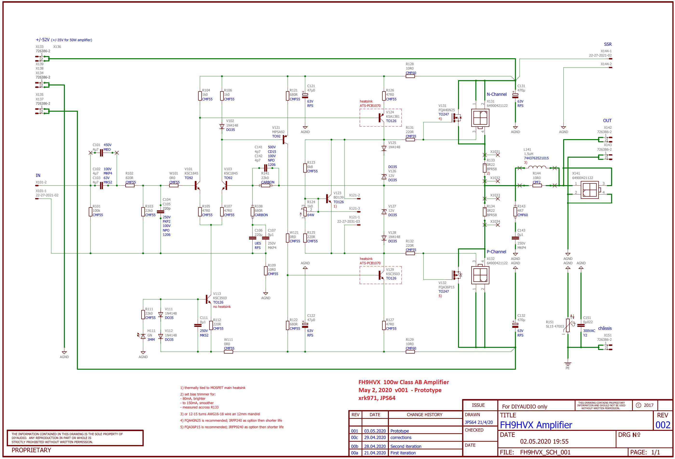
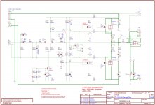
The current schematic looks more like this. The CCS was changed to KSC3503, an LED was added as an indicator at the base of the CCS. Some resistor values are still being tweaked but it seems Vunce is having pretty good luck with 1k and 220R above and below the LTP. There may be a few other changes before we get the manufacturing ready schematic (like power supply 2 pin Molex KK for the SSR) and PSU Fastons on either side of the board selectable via solder jumper.
Attachments
Last edited:
@Manniraj,
I apologize for the dim pictures, I was trying to capture the lit LED’s.
You have good eyes! Yes, I tapped V+ off the 10R resistor leg, it was the easiest location without removing the board from the heatsink. The GND is picked up from the GND faston on one board and at the psu GND for the other board.
Like X said, adding the Molex 2-pin header will make this connection a simple plug’n’play
@Meanie,
Hahaha!! Yes, as far as generated heat, this amp is certainly not like the space heaters we’ve been working on. Would be perfect for your HOT summers.
Thanks Vunce, its very clear now.
That’s 140mA across the source resistors. So 0.235ohms (parallel 0.47R) x 0.140A = 0.033V on the DVM.
Your boards that I was using it earlier which went bad because of a stray solder pin, were being run at based on your above calculation as:
0.235ohms (parallel 0.47R) x 0.212A = 0.050V on the DVM
As I had measured and set the bias at 50mV (volts) on the DVM using the 0.47R resistor close negative terminal. It was running a little bit warm but very very nice. I am now trying to bring it back with some parts damaged especially those 12V diodes. Because of the lockdown no shipping is possible, need to wait till the end of this month.
I just ran some more LTspice sims of the FH9HVX with a 4ohm load as Vunce says he wants to bring it to his brother's house to test out on some big Polk LSi15's.
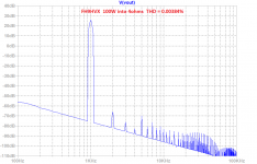
Well at 100w into 4ohms (150mA quiescent bias), we get very nice performance of THD at 0.0038%. So looks like this amp has no problem driving 4ohm speakers.
Harmonic profile still looks excellent, in fact H2 dominant and H3 less than H2 and descending higher orders, with 5th a bit higher than 4th and descending from there.

Well at 100w into 4ohms (150mA quiescent bias), we get very nice performance of THD at 0.0038%. So looks like this amp has no problem driving 4ohm speakers.
Harmonic Frequency Fourier Normalized Phase Normalized
Number [Hz] Component Component [degree] Phase [deg]
1 1.000e+03 2.825e+01 1.000e+00 -1.40° 0.00°
2 2.000e+03 7.293e-04 2.582e-05 128.23° 129.63°
3 3.000e+03 2.203e-04 7.799e-06 -141.95° -140.55°
4 4.000e+03 1.030e-04 3.648e-06 170.91° 172.31°
5 5.000e+03 4.479e-04 1.586e-05 -112.40° -111.00°
6 6.000e+03 1.336e-04 4.729e-06 167.76° 169.16°
7 7.000e+03 2.154e-04 7.626e-06 -119.66° -118.26°
8 8.000e+03 1.084e-04 3.838e-06 164.17° 165.57°
9 9.000e+03 1.339e-04 4.740e-06 -125.16° -123.76°
10 1.000e+04 9.661e-05 3.420e-06 160.33° 161.73°
11 1.100e+04 6.880e-05 2.436e-06 -133.55° -132.16°
12 1.200e+04 8.557e-05 3.029e-06 156.43° 157.82°
13 1.300e+04 2.655e-05 9.398e-07 -152.27° -150.88°
14 1.400e+04 7.627e-05 2.700e-06 152.59° 153.98°
15 1.500e+04 1.227e-05 4.344e-07 99.70° 101.10°
Total Harmonic Distortion: 0.003384%(0.008700%)
Harmonic profile still looks excellent, in fact H2 dominant and H3 less than H2 and descending higher orders, with 5th a bit higher than 4th and descending from there.
Attachments
Last edited:
Your boards that I was using it earlier which went bad because of a stray solder pin, were being run at based on your above calculation as:
0.235ohms (parallel 0.47R) x 0.212A = 0.050V on the DVM
As I had measured and set the bias at 50mV (volts) on the DVM using the 0.47R resistor close negative terminal. It was running a little bit warm but very very nice. I am now trying to bring it back with some parts damaged especially those 12V diodes. Because of the lockdown no shipping is possible, need to wait till the end of this month.
You could just make a new amp when the new boards arrive.
Ready for Prototype PCB's
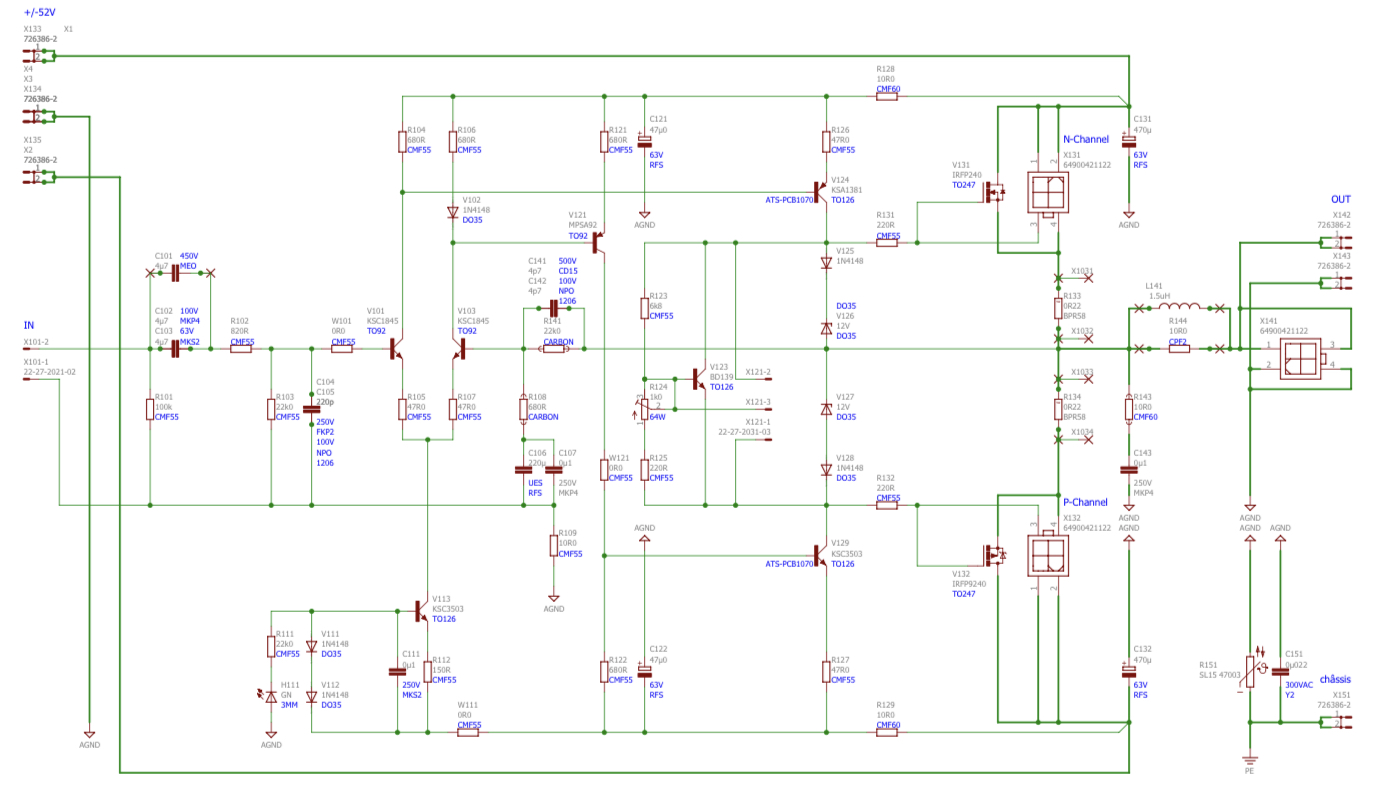
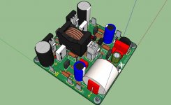
I just got the finalized manufacturing data files from JPS64. Here is how the amp looks, plus schematic, BOM, and stuffing diagram.

Thank you, JPS64 for another awesome layout!
I just got the finalized manufacturing data files from JPS64. Here is how the amp looks, plus schematic, BOM, and stuffing diagram.
Thank you, JPS64 for another awesome layout!
Attachments
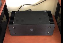
Vunce just shared with me a photo of his new baby all buttoned up.
Nice build Vunce!
https://www.diyaudio.com/forums/gro...s-100w-class-ab-lean-times-5.html#post6188402
Hi Gary,
Yes, I was going to wait until the prototypes were verified but it seems the pre-proto build by Vunce shows this amp is going to work out just fine at 100w. I’ll go ahead and start up a GB list.
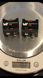
Those are standard items from Mouser. There are similar ones in SMT which I have used before. They are very nice inductors with negligible DCR.
Yes, I was going to wait until the prototypes were verified but it seems the pre-proto build by Vunce shows this amp is going to work out just fine at 100w. I’ll go ahead and start up a GB list.
Those are standard items from Mouser. There are similar ones in SMT which I have used before. They are very nice inductors with negligible DCR.
FH9HVX GB interest list. 100mm x 100mm boards will be 2mm thick with 2oz copper and ENIG finish. Please add your name, number of boards, and country. Price will be $23 each. Shipping will be usual auto calculated First Class package with tracking per Etsy shop.
Name / Qnty / Country
Name / Qnty / Country
Last edited:
- Home
- Group Buys
- FH9HVX - Budget Conscious 100w Class AB for Lean Times