Jhofland and I are pleased to introduce the long-awaited Soft as a Feather Pillow (SFP) solid state relay (SSR) soft start circuit for use with power amplifiers. The development for this circuit has actually been going on for a long time, you will notice that the board design is at v2.1.
The goals of this circuit were to provide a gentle in-rush current limiter using a bank of power resistors during initial turn on, and then having a low Rdson MOSFET bypass the resitors after a set amount of time. By using a SSR vs a mechanical realy, we eliminate a source of arcing and wear, and the switchover is silent - no clacking of relays. Another goal of this circuit was to provide an added benefit of providing an open collector logic signal that can be used in conjunction with a speaker protection SSR that will tell it to instantly shut the speakers off if the voltage rail of the small on-board 5v SMPS turns off.
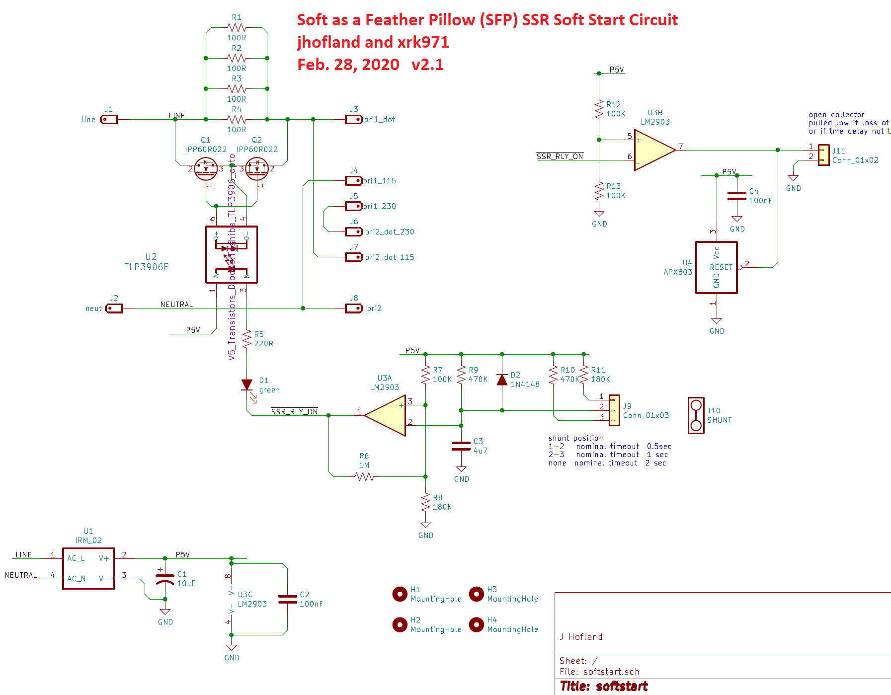
A special SSR ultra-low Rdson MOSFET was chosen that is rated for 600v, 23A, and has an Rdson of 22mOhms. This SFP can basically soft start almost any power amplifier in DIYA. With a low Rdson value of 44mOhm for two in series, we will have very low dissipation for even higher bias current Class A amplifers. The MOSFET is controlled with the usual opto-coupler and the start on time delay is controlled by a selectable RC circuit and comparator. Variable turn on time delays ranging from 0.5 sec, 1 sec, and 2 seconds is available via a jumper setting.
Here is the schematic:
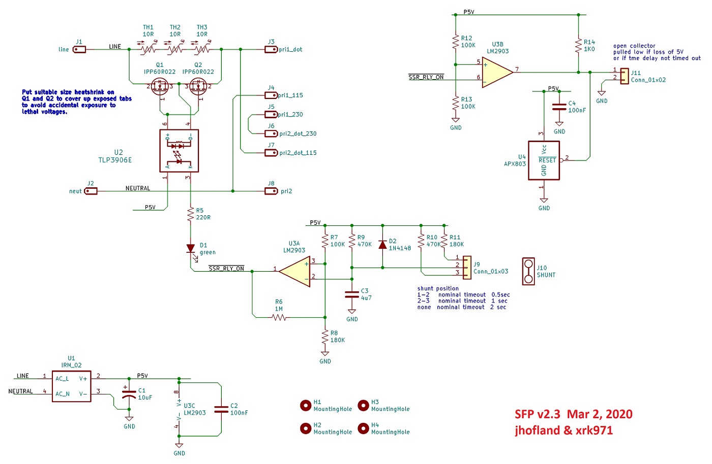
Edit Mar 3, 2020 revised v2.3 schematic with NTCs instead of resistors:
BOM for v2.3 here:
https://www.diyaudio.com/forums/attachment.php?attachmentid=821923&d=1583218278
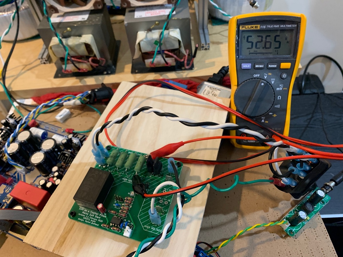
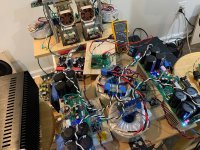
Here is the verification unit undergoing testing with the Omega amplifier:
https://www.diyaudio.com/forums/att...soft-start-circuit-gb-sfp-v2-1-test-setup-jpg
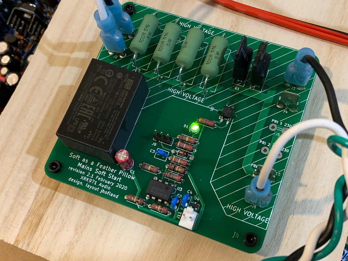
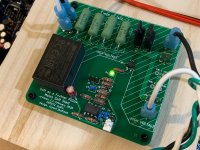
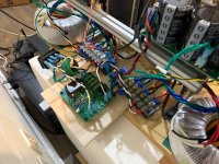
Here is a closeup of the board in action:
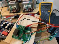
At turn-on, about 52Vac is registered across the four 100ohm (5w ea) wirewound resistors:
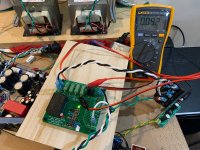
2 seconds later, the SSR kicks in and the voltage drops to about 92mVac:

A clamp on current meter showed that the amp was drawing 1.62Arms at the wall plug. So the dissipation across the MOSFETs is only about 150mW. An earlier
I will continue testing out over the next few days to ensure tha everything works out well.
Edit Dec 17, 2023: including the schematic and BOM to the latest variant called the SFPP (SFP Plus) which includes remote turn on/off with a momentary SPDT switch with LED indicator. Great for low voltage front panel power switches with ring LED.
https://www.diyaudio.com/community/...ssr-soft-start-circuit-gb.350441/post-7538507

The goals of this circuit were to provide a gentle in-rush current limiter using a bank of power resistors during initial turn on, and then having a low Rdson MOSFET bypass the resitors after a set amount of time. By using a SSR vs a mechanical realy, we eliminate a source of arcing and wear, and the switchover is silent - no clacking of relays. Another goal of this circuit was to provide an added benefit of providing an open collector logic signal that can be used in conjunction with a speaker protection SSR that will tell it to instantly shut the speakers off if the voltage rail of the small on-board 5v SMPS turns off.
A special SSR ultra-low Rdson MOSFET was chosen that is rated for 600v, 23A, and has an Rdson of 22mOhms. This SFP can basically soft start almost any power amplifier in DIYA. With a low Rdson value of 44mOhm for two in series, we will have very low dissipation for even higher bias current Class A amplifers. The MOSFET is controlled with the usual opto-coupler and the start on time delay is controlled by a selectable RC circuit and comparator. Variable turn on time delays ranging from 0.5 sec, 1 sec, and 2 seconds is available via a jumper setting.
Here is the schematic:
Edit Mar 3, 2020 revised v2.3 schematic with NTCs instead of resistors:
BOM for v2.3 here:
https://www.diyaudio.com/forums/attachment.php?attachmentid=821923&d=1583218278
Here is the verification unit undergoing testing with the Omega amplifier:
https://www.diyaudio.com/forums/att...soft-start-circuit-gb-sfp-v2-1-test-setup-jpg
Here is a closeup of the board in action:
At turn-on, about 52Vac is registered across the four 100ohm (5w ea) wirewound resistors:
2 seconds later, the SSR kicks in and the voltage drops to about 92mVac:
A clamp on current meter showed that the amp was drawing 1.62Arms at the wall plug. So the dissipation across the MOSFETs is only about 150mW. An earlier
I will continue testing out over the next few days to ensure tha everything works out well.
Edit Dec 17, 2023: including the schematic and BOM to the latest variant called the SFPP (SFP Plus) which includes remote turn on/off with a momentary SPDT switch with LED indicator. Great for low voltage front panel power switches with ring LED.
https://www.diyaudio.com/community/...ssr-soft-start-circuit-gb.350441/post-7538507
Attachments

Last edited:
I forgot to mention that in testing this circuit last night, there was a total absence of turn-on speaker thump. The soft start current slowly ramps up the amp main supply. Only silence at the speakers. Nice!
I forgot to mention that in testing this circuit last night, there was a total absence of turn-on speaker thump. The soft start current slowly ramps up the amp main supply. Only silence at the speakers. Nice!
Well done. That's what I like to hear .. nothin'.
I just tested the remote speaker protection logic and it works as designed. There is a 2-pin Molex KK connector that is supposed to work as an open-collector output to a logic device. So a suitable external DC voltage (not the built in 5v SMPS), say the one from a separate logic circuit can be connected to the pin 1 logic output via a pullup resistor (10k for example). I used a 9v battery and a 12k resistor connected to Molex KK pin 1. When the AC mains power is applied to the SFP, the voltage below the pullup will go low until the SSR on the SFP switches on, after which it will show the 9v battery voltage. Upon turning off the AC mains to the SFP, the on-board 5v SMPS drops below a threashold (4.63v in this case) that is detected by voltage supervisor, and the output goes low. In this way, this can be used to effect a speaker protection SSR that has a built in quick turn-off logic. This is actually a feature that will be available on the Gen 2 RTR SSR speaker protection circuit. The idea is to disconnect the speakers from the amp output the moment mains is shut off, rather than wait for the large caps on the PSU to slowly drain away while letting the speakers stay connected.
So the SFP has been fully verified to work as designed now.
So the SFP has been fully verified to work as designed now.
I think we are ready to start a list of interest for this PCB. They will be 1.6mm thick with 2oz copper and ENIG finish. Price will be $23. Shipping will be the usual as determined by Etsy for USPS First Class package with tracking.
Please add your name to the running list below with number of boards and country.
SFP GB Interest List
For example:
Johndoe 2 boards USA
Please add your name to the running list below with number of boards and country.
SFP GB Interest List
For example:
Johndoe 2 boards USA
There are two really easy to solder SMT parts (4 pins on TLP3906E and 3 pins on the APX803 voltage supervisor). These parts have exposed legs so quite easy to do with a standard soldering iron. But in case you want me to preinstall these parts for you, I can do that but it will be $13 extra per board.
I just installed the SFP on my biggest Class A amp, the Glass Harmony, designed by Hugh Dean. It is a 50w SE Class A amp (truly single 37v rail at 4.7A bias current and uses a 67mH microwave oven transformer for the reactive load. It is a dual monobloc design and I had two separate wall plugs and IECs before. I have now consolidated the mains AC input to one SFP which then feeds two separate ANTEK AN-5434 trafos. It works like a charm now and I bought myself almost an extra volt of headroom because I don't have to suffer the voltage drop through the hot 8D-20 NTC. I might be closer to 52w now. The other bonus is no more turn on speaker thump!

Attachments
Thanks for the show of interest guys. Looks good enough for me to set up pre-orders on my Etsy shop. Will try to get these in as soon as possible. It looks like Covid19 is adding about 5 days delay on manufacturing from China/HK.
The SFP is now available as a pre-order in my shop:
Soft as a Feather Pillow SFP Solid State Relay SSR Soft | Etsy
Soft as a Feather Pillow SFP Solid State Relay SSR Soft | Etsy
I’m curious to know the reasoning behind using power resistors instead of a NTC Thermistor in this application.
Best,
Anand.
Best,
Anand.
Hi X,
What is the max VA that can be drawn through this soft start circuit, and I presume the resistor value is for use on both 110V and 230V AC inputs?
Regards, Kevin
What is the max VA that can be drawn through this soft start circuit, and I presume the resistor value is for use on both 110V and 230V AC inputs?
Regards, Kevin
The MOSFETs are rated at 27A max provided a heatsink is used. A heatsink would require insulated bushings and insulator pads to keep the mains voltage off the sink. Anything above 5A, I would use a small stamped aluminum heatsink.
The Rdson is about 25mohm. Power dissipation is i^2R. So for 10A that’s 2.5W.
The Rdson is about 25mohm. Power dissipation is i^2R. So for 10A that’s 2.5W.
I’m curious to know the reasoning behind using power resistors instead of a NTC Thermistor in this application.
Best,
Anand.
NTC is meant to be temperature variable resistor that acts as passive soft start. What’s nice about using resistors is that they are always high resistance, in this case, 25ohms. An NTC may start out out at 20ohms cold but when hot become 0.5ohms. If hot, and power is cut momentarily for a few seconds and flipped back on, the NTC will act like a 0.5ohm resistor and not 20ohm. Then you lose your soft start capability to limit current. That doesn’t happen with big power resistors. Once the system charges up at low current limited by the 25ohm bank of resistors, the SSR kicks in and bypasses their resistors with the 25mOhm MOSFET.
In this way, the system doesn’t suffer the additional steady state voltage drop of the NTC when operating steady state. You gain a little headroom in voltage for free.
- Home
- Group Buys
- Soft as a Feather Pillow (SFP) SSR Soft Start Circuit GB