Yeah I think the switch is a 'break before make' for changing inputs.
I was intending to break the line between the 10R/3W and the 24VDC feed pad and insert a switch there but that will still leave the 230VAC connected so I haven't decided what to do other than yanking the cord each time.
I was intending to break the line between the 10R/3W and the 24VDC feed pad and insert a switch there but that will still leave the 230VAC connected so I haven't decided what to do other than yanking the cord each time.
I have my PCB now..yeah, thank you very much. Arrived looking like it had a tough trip.
I'm trying to get my head around the jfets needed, and this is going to be a newbie question.
I assume the PCB needs 8 JFET, 2SK370 or 170-GR, N-CH, Matched?
Thanks for the arrow.com recommendation great place.
I'm trying to get my head around the jfets needed, and this is going to be a newbie question.
I assume the PCB needs 8 JFET, 2SK370 or 170-GR, N-CH, Matched?
Thanks for the arrow.com recommendation great place.
:-o looks like it was delivered by a pack of wild dogs.
That's right. And best to match all 8 as close as possible. There is another part number available to use as well -J113. This needs additional resistors. There is some build tips a bit further back in this thread.
I ordered 50 2sk170gr from eBay and found out later they were coming from UTSource, who don't have a great reputation on here with regard to legitimate parts.
The items I got are physically correct with respect to the casing and markings but I have not set about electrically testing their properties yet.
Good luck with the build and make sure you remember to implement the changes in the PCB corrections PDF that should have been emailed to you when you paid for shipping.
There is another part number available to use as well -J113. This needs additional resistors.
Does anybody know what the resistor value must be when using J113's?
The resistor value is picked depending on the IDSS of the Jfet.
There is a bit more information on the B1 thread:
B1 with Korg Triode
There is a bit more information on the B1 thread:
B1 with Korg Triode
This was the other side...That looks like it's been run over chilly😱
The board is slightly bowed now. 🙁

Hi GASCo. Here answers to your questions:
-The board is designed for 1/4W resistors. However the CFM55 resistors are all 1/4W body size, but depending on the type can be rated 0.25W, or 0.5W (but the body doesn't change). This is because the CFM55 are military grade resistor, normally 0.5W rating for civil use, but derated down to 0.25W for the military. To resume if o=you order CFM55 resistors, they will fit...
-R4 original value of 270R was to drop the 24V up to 9V, and still allows enough current for the zener to work. The 9V sinks about 17ma, so 270R x 17ma = 4.6V, plenty is left for the zener to work at 9V. 330R X 17ma = 5.6V, very close to the 270R value. It will work with the zener without problem...
-The front switch is only for input selection (In1 or In2), the pcb is always powered, there is no power-on switch.
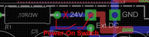
-One solution as some suggested, is to use the +24V TP and R1 resistor leg to add a switch, see picture. Simply cut the bottom trace between the 24VTP, and the indicated R1 resistor leg and add a siwtch there. It will disconnect the 24V Supply from the CRC filter and preamp. Indeed the 24V SMPS will stay On, and well as the smd part, but that can be view as a standby mode, supply stays On, when the preamp is off...
-The board is designed for 1/4W resistors. However the CFM55 resistors are all 1/4W body size, but depending on the type can be rated 0.25W, or 0.5W (but the body doesn't change). This is because the CFM55 are military grade resistor, normally 0.5W rating for civil use, but derated down to 0.25W for the military. To resume if o=you order CFM55 resistors, they will fit...
-R4 original value of 270R was to drop the 24V up to 9V, and still allows enough current for the zener to work. The 9V sinks about 17ma, so 270R x 17ma = 4.6V, plenty is left for the zener to work at 9V. 330R X 17ma = 5.6V, very close to the 270R value. It will work with the zener without problem...
-The front switch is only for input selection (In1 or In2), the pcb is always powered, there is no power-on switch.
-One solution as some suggested, is to use the +24V TP and R1 resistor leg to add a switch, see picture. Simply cut the bottom trace between the 24VTP, and the indicated R1 resistor leg and add a siwtch there. It will disconnect the 24V Supply from the CRC filter and preamp. Indeed the 24V SMPS will stay On, and well as the smd part, but that can be view as a standby mode, supply stays On, when the preamp is off...
Attachments
Last edited:
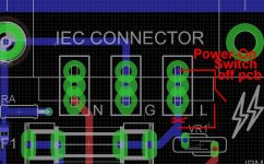
An other possible mods for the power-on, that includes the 24V SMPS is to cut the AC directly at the input, see picture. You can cut the Live trace (under the PCB, and run a switch from the AC inlet Live pin, and then back to the pcb. Make sure to use an AC line rated switch to do so.
If you don't use the specified enclosure, and you can mount the AC inlet away from the PCB, it is even easier, no pcb mod to do, simply cut the AC Line wire with a switch, before connecting to the pcb...
SB
If you don't use the specified enclosure, and you can mount the AC inlet away from the PCB, it is even easier, no pcb mod to do, simply cut the AC Line wire with a switch, before connecting to the pcb...
SB
Attachments
Your PCB received unscathed and intact here in UK. Outer envelope wasn't to badly scathed.
Many thanks for your time and effort with this.
Raymondj
Many thanks for your time and effort with this.
Raymondj
I'm placing a small order of pcb for some other projects, I can order a few extra B1-Nutube if there is still some interest, not more than 5 pcb to limit the shipping cost to me.
Let me know...
Thanks
SB
Let me know...
Thanks
SB
- Home
- Group Buys
- GB B1 Nutube PCB with integrated PS