With 15.6dB and 15.6dB of M2X, you have about 31dB overall which should be perfect for driving with a cellphone or usual RCA source.
RCA it is, CD, streamer and TT via phono stage.
Hi Xrk,
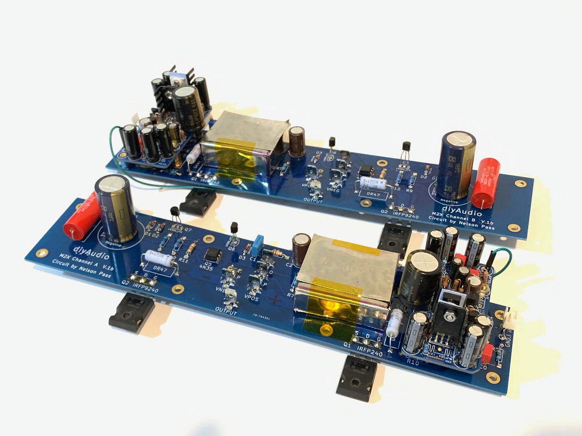
Just build and tested my 4 boards intended for a M2/lxmini project.
I only had 20v dual Psu at hand, bias is approx. 320mV which looks fine, but offset is in the +80mV region, I would like to trim the offset to near zero, so I can have the choice to use the M2 without the trafo. Which resistor could be tweaked preferably with a trimpot in parallel on the bottom pcb side?
Regards, Albert
Hi Asanden,
Thanks for building it and getting it to work. The offset is a combination of the variations Vce on the transistors and the Vgs on the MOSFET and the variations in the resistors. However, the offset can probably be trimmed by replacing the 61.9R resistor R103 with a 200R multi turn pot and adjusting to get 0mV at warmed up operating temp. Remove the pit and measure the value and replace with an exact resistor. If you run out of room and cannot reach zero, replace R104 (14.9kv resistor below it with something like 14.7k and use a 1k pot above for larger range.
Thanks for building it and getting it to work. The offset is a combination of the variations Vce on the transistors and the Vgs on the MOSFET and the variations in the resistors. However, the offset can probably be trimmed by replacing the 61.9R resistor R103 with a 200R multi turn pot and adjusting to get 0mV at warmed up operating temp. Remove the pit and measure the value and replace with an exact resistor. If you run out of room and cannot reach zero, replace R104 (14.9kv resistor below it with something like 14.7k and use a 1k pot above for larger range.
Hi Asanden,
Thanks for building it and getting it to work. The offset is a combination of the variations Vce on the transistors and the Vgs on the MOSFET and the variations in the resistors. However, the offset can probably be trimmed by replacing the 61.9R resistor R103 with a 200R multi turn pot and adjusting to get 0mV at warmed up operating temp. Remove the pit and measure the value and replace with an exact resistor. If you run out of room and cannot reach zero, replace R104 (14.9kv resistor below it with something like 14.7k and use a 1k pot above for larger range.
Thanks for the info, I will try it out
Melbourne in M2X Test
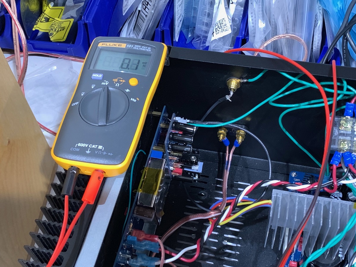
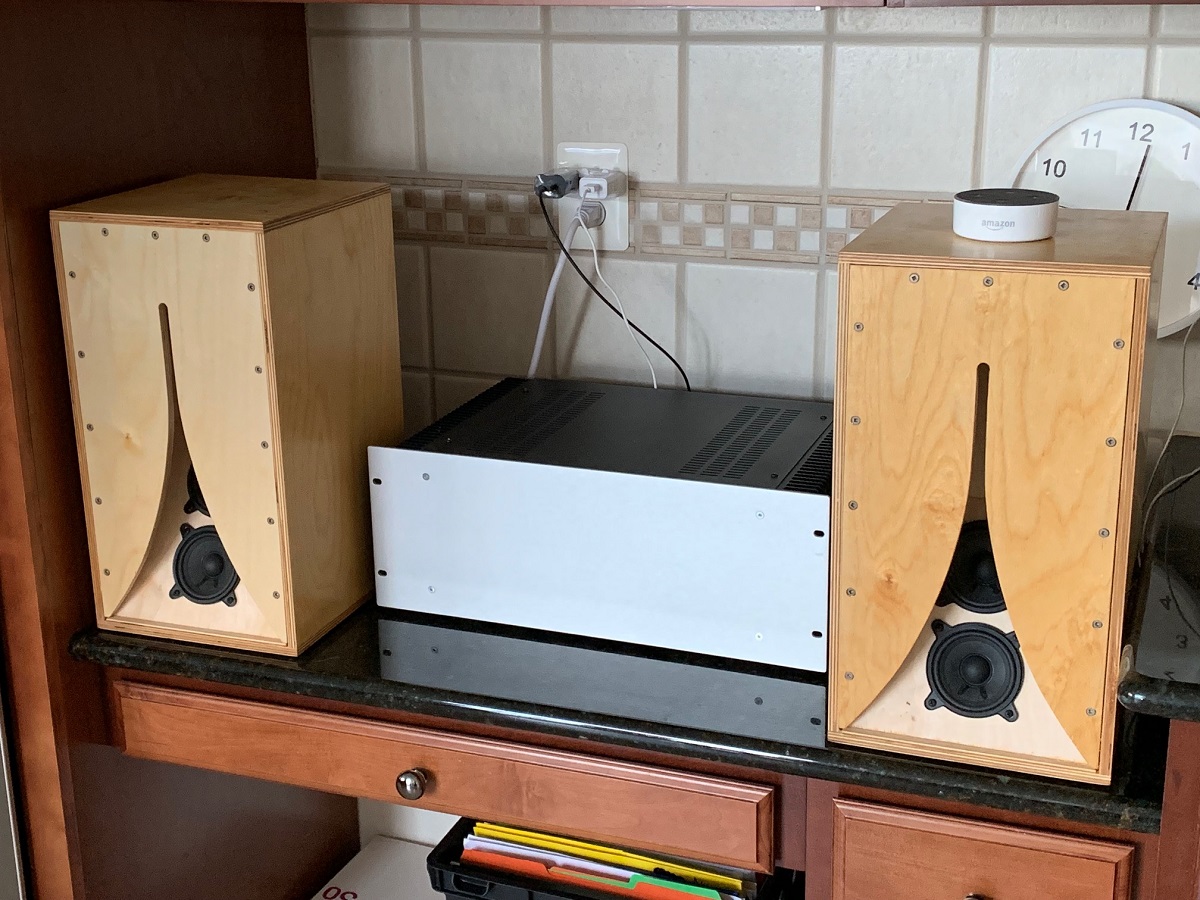
The Melbourne works very well inside the M2X as an input stage daughter board. It took me quite sometime to debug a shrieking oscillation that would result whenever I connected a source to the RCA input. Finally figured it out - it requires that the ground on the Melbourne be connected to the PSU star hub GND, and not the local GND on the M2X board. Also, the Melbourne needs to be DC-coupled to the Edcor (use of a 220uF cap seems to induce some sort of LC circuit that shrieks at circa 2khz to 5kHz). Once this was resolved, I was treated to a very quiet amp - now measuring 100uV rms at the speaker output with input turned off. The gain on the Melbourne using 33k and 5k6 pair gives 15.6dB, which is a good match for sources like a phone, mp3 player, or Bluetooth source. I have been testing with an Amazon Echo Dot or Echo Input. The sound is very nice - great bass, wide soundstage, clear imaging, and a pleasant articulate, and natural sound.
This M2X is using the SLB PSU, more details on that here.
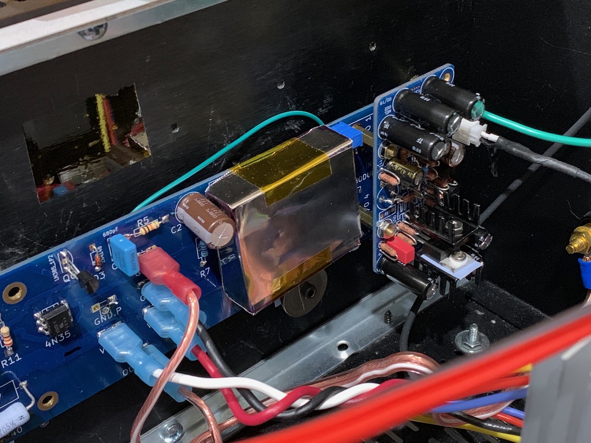
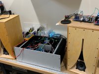
Melbourne's mounted on M2X (note that output coupling cap is shown here, but had to be removed):
Detail of left channel:
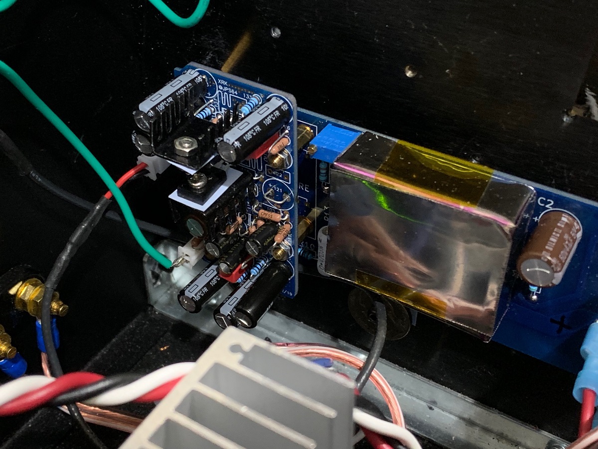
Detail of Right channel (note green wire from Melbourne GND to SLB PSU star hub Gnd point):
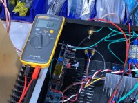
Fluke 101 noise measurement at amp output with source off:
Initial listening on the bench:

Longer term listening upstairs:
The Melbourne works very well inside the M2X as an input stage daughter board. It took me quite sometime to debug a shrieking oscillation that would result whenever I connected a source to the RCA input. Finally figured it out - it requires that the ground on the Melbourne be connected to the PSU star hub GND, and not the local GND on the M2X board. Also, the Melbourne needs to be DC-coupled to the Edcor (use of a 220uF cap seems to induce some sort of LC circuit that shrieks at circa 2khz to 5kHz). Once this was resolved, I was treated to a very quiet amp - now measuring 100uV rms at the speaker output with input turned off. The gain on the Melbourne using 33k and 5k6 pair gives 15.6dB, which is a good match for sources like a phone, mp3 player, or Bluetooth source. I have been testing with an Amazon Echo Dot or Echo Input. The sound is very nice - great bass, wide soundstage, clear imaging, and a pleasant articulate, and natural sound.
This M2X is using the SLB PSU, more details on that here.
Melbourne's mounted on M2X (note that output coupling cap is shown here, but had to be removed):
Detail of left channel:
Detail of Right channel (note green wire from Melbourne GND to SLB PSU star hub Gnd point):
Fluke 101 noise measurement at amp output with source off:
Initial listening on the bench:
Longer term listening upstairs:
Attachments


Last edited:
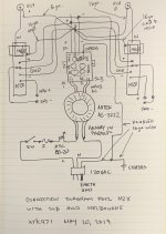
Here is a grounding connection diagram for the Melbourne on M2X and SLB PSU. Note that on the new SLB due to arrive any day now, plenty of ground Faston spades are available directly on the board to serve as the star hub. I had to use a terminal block which is not as good. It may be overkill but I used quality stranded copper 16 gauge wire for all the grounding lines to the star hub. I doubled up the 16 gauge wires between the PSU to chassis and to earth mains ground.
If you are using a dual SLB and dual trafos, this doesn’t t apply and ground loop hum is much less of an issue.
If you are using a dual SLB and dual trafos, this doesn’t t apply and ground loop hum is much less of an issue.
Attachments
I am going to handle GBs via Etsy to see if it helps me with the logistics. Melbourne DB’s are available here:
Melbourne Class A preamplifier daughterboards | Etsy
Melbourne Class A preamplifier daughterboards | Etsy
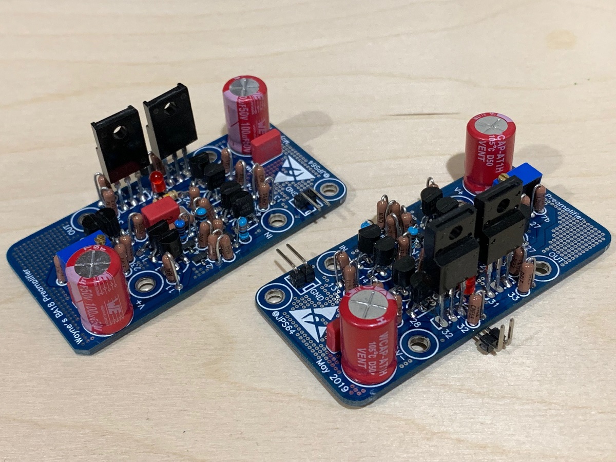
FYI, the WBA18 preamp module has now been verified to work (at least from steady bias current and adjustble DC offset). Still need to install in amp and listen but looks promising.
So I am about to submit my parts order, and discovered some of the parts are back ordered.
The jfets seem to have been cleared out nearly everywhere.
Has anyone used Utsource? They are based in India, and have the jfets in stock.
C102 and C122: 1u0
C106 and C111: 47u0
C131, C132, C133, C134, C135, C136: 470u
These are all back ordered. Is there any reason not to use the same parts but with higher voltages or temps if available?
Could I get some clarification on this
(5.6+33)/5.6 = 6.89 != 15.56
(1+33)/1 = 34 != 30.6
did we leave a logarithm out someplace?
The jfets seem to have been cleared out nearly everywhere.
Has anyone used Utsource? They are based in India, and have the jfets in stock.
C102 and C122: 1u0
C106 and C111: 47u0
C131, C132, C133, C134, C135, C136: 470u
These are all back ordered. Is there any reason not to use the same parts but with higher voltages or temps if available?
Could I get some clarification on this
The default gain is 15.6dB and is set by the (R118+R119)/R118 value of (5k6+33k)/5k6. If you want 30.6dB if gain use 1k for R118 etc. leave R119 at 33k.
(5.6+33)/5.6 = 6.89 != 15.56
(1+33)/1 = 34 != 30.6
did we leave a logarithm out someplace?
Gain of 34x in dB is 20 x log(34)=30.6dB
Thanks,
any thoughts on my other questions?
Really appreciate all the effort on this and other items.
-Josh
Mouser has 11,000 of 2sk209 in stock.
2SK209-GR(TE85L,F) Toshiba | Mouser
On the caps, those are commonly available parts and you are welcome to substitute for other brands etc. just make sure values and voltages and pin spacing the same. Also those are film caps.
2SK209-GR(TE85L,F) Toshiba | Mouser
On the caps, those are commonly available parts and you are welcome to substitute for other brands etc. just make sure values and voltages and pin spacing the same. Also those are film caps.
I built up the Melbourne boards a a headphone amp - posted on the HPA thread but thought people here may also be interested.
Post/pics here:
The Melbourne Class A Headphone Amp and Pre-amp
Post/pics here:
The Melbourne Class A Headphone Amp and Pre-amp
Mouser has 11,000 of 2sk209 in stock.
2SK209-GR(TE85L,F) Toshiba | Mouser
On the caps, those are commonly available parts and you are welcome to substitute for other brands etc. just make sure values and voltages and pin spacing the same. Also those are film caps.
I was unclear, and said JFET when I meant BJT. Sorry for asking the wrong question, and I appreciate you taking the time to answer it.
What I meant to ask was, is there a replacement for V122?
V122, KSA1381, TO126V, KSA1381ESTU, Bipolar Transistors - BJT PNP Si Transistor Epitaxial
And has anyone used Utsource?
KSA1381ESTU Fairchild Semiconductor Corporation | Elec-component | UTSOURCE
If you have time, I would like some further clarification:
from post #1
Please note that the parts list below has a few errors (the schematic is correct):
1. R114 should be 0.1% tolerance metal thin film
2. R116 should be 0.1% tolerance metal thin film
3. C116 should be NP0/C0G 100v
In the current Mouser shared shopping cart (BTW I can't thank people enough for this) R114 and R116 are listed as 1.0% and are regular metal film.
R114 in particular is fusible.
Should this be a fusible resistor?
There seems to be a suitable thin film 0.1% 100R for R116
Vishay 100 Ohms 0.1 % Thin Film Resistors - Through Hole | Mouser
The only thin films in 0.1% for R114 are fairly large SMD, and I am not sure they will fit between the pads.
There are 1.0% thin films in through hole though
47 Ohms Thin Film Resistors - Through Hole | Mouser
What is more important? Thin film or tolerance? 0.1% of 47 is 0.047ohms, a bit of a pain to measure that repeatedly if I buy a pile of them and sort them.
Or should I try to shoe horn the SMD part in?
Thanks again,
-Josh
P.S. I downloaded the Mouser cart and merged it with the parts list so part ID's can be easily connected to part numbers.
Once I make the substitions, I will up load it for others.
You can use TTA004 as substitute for KsA1381. The one you linked looks good actually.
The resistors that have specified tolerance, the tolerance is important to get the dC offset low of you will be using DC coupled version. Metal thin film has better distortion performance. I would not worry about it too much. Hey whatever you can fit bit values are more important.
The resistors that have specified tolerance, the tolerance is important to get the dC offset low of you will be using DC coupled version. Metal thin film has better distortion performance. I would not worry about it too much. Hey whatever you can fit bit values are more important.
- Status
- This old topic is closed. If you want to reopen this topic, contact a moderator using the "Report Post" button.
- Home
- Group Buys
- Melbourne Daughterboard for M2X