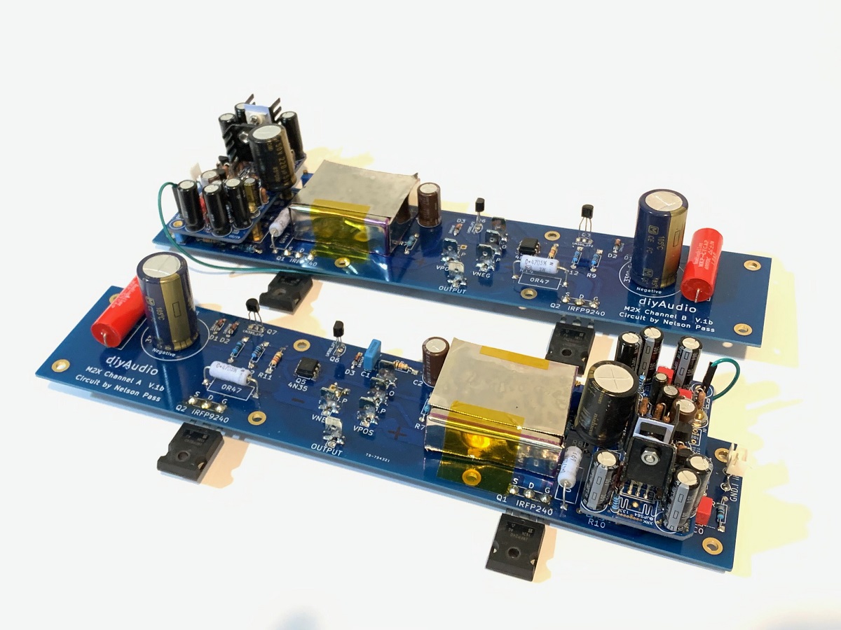
I finally found some time to start putting the boards together - bit tight to say the least. I find myself wishing you had offered an SMD option, I think it would be much easier to assemble.
Can I get some clarity on jumpers?
x132 looks to be 0V. Can this be left floating, or do I need to send it to clean ground?
More importantly, will something fry if left floating?
Looking over the several threads Melbourne is posted over, I see some with jumpers running to the screw posts. Are any of these used when using the Melbourne purely as a daughter board for the M2x?
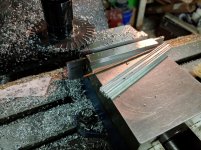
Lastly, I forgot to order heatsinks, and all the spares I have are too large.
I can fabricate something in the machine shop, or I can just bolt the actives to some aluminum bar stock. How much heat sinking is needed?
Thanks,
-Josh
Can I get some clarity on jumpers?
x132 looks to be 0V. Can this be left floating, or do I need to send it to clean ground?
More importantly, will something fry if left floating?
Looking over the several threads Melbourne is posted over, I see some with jumpers running to the screw posts. Are any of these used when using the Melbourne purely as a daughter board for the M2x?
Lastly, I forgot to order heatsinks, and all the spares I have are too large.
I can fabricate something in the machine shop, or I can just bolt the actives to some aluminum bar stock. How much heat sinking is needed?
Thanks,
-Josh
Hi Josh,
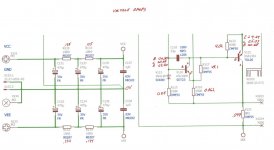
If your using the Melbs for the Yarra preamp, I attached a picture showing the omitted components and jumper locations circled in red.
I’m not familiar with the setup for the M2 though.
The transistors do get a bit hot, fit the biggest heatsink you can fab for the tight spot.
If your using the Melbs for the Yarra preamp, I attached a picture showing the omitted components and jumper locations circled in red.
I’m not familiar with the setup for the M2 though.
The transistors do get a bit hot, fit the biggest heatsink you can fab for the tight spot.
Attachments
Well, I just went ahead and sinks.
2 hours work for $2.00 worth of parts 🙂
Any input on my earlier questions?
@Vunce,
The Melbourne is set up differently for the M2x, and is used only as an input stage with fixed gain.
-Josh
2 hours work for $2.00 worth of parts 🙂
Any input on my earlier questions?
@Vunce,
The Melbourne is set up differently for the M2x, and is used only as an input stage with fixed gain.
-Josh
Attachments
Well, I just went ahead and sinks.
2 hours work for $2.00 worth of parts 🙂
-Josh
That’s awesome Josh!!
When can I put my order in for a dozen heatsinks 😀
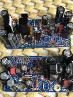
I hooked up the Melbourne to my M2x, and I am getting almost no output.
I have to turn the volume up to almost max on the preamp before I start hearing music.
There is also a constant hum coming from the speakers.
I connected x132 to the 0V reference on my power supply.
I looked the boards over closely, and I see nothing amiss.
I noticed in this post
in this thread
AKSA Lender Pass Hybrid M2 (ALPH-M2) Amp
There are extra jumpers to Melbourne.
Have I missed something?
Will post pics of anything people want.
Thanks,
-Josh
I have to turn the volume up to almost max on the preamp before I start hearing music.
There is also a constant hum coming from the speakers.
I connected x132 to the 0V reference on my power supply.
I looked the boards over closely, and I see nothing amiss.
I noticed in this post
The Melbourne has now been officially tested with the M2X and it sounds great!
Melbourne Daughterboard for M2X
The M2X also benefits from an SLB PSU. Super quiet 100uV rms output noise now.
in this thread
AKSA Lender Pass Hybrid M2 (ALPH-M2) Amp
There are extra jumpers to Melbourne.
Have I missed something?
Will post pics of anything people want.
Thanks,
-Josh
Have you measured the bias current in the Melbourne? It would be advisable to hook up a +/-24v bench supply to an unconnected one and check to see if it works.
Some high resolution photos would be good.
Some high resolution photos would be good.
Have you measured the bias current in the Melbourne? It would be advisable to hook up a +/-24v bench supply to an unconnected one and check to see if it works.
Some high resolution photos would be good.
Thanks for the reply.
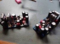
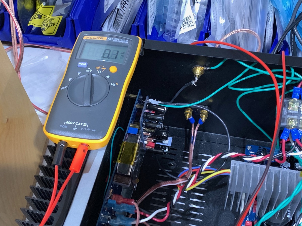
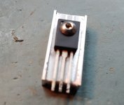
I measured across the test pads and got a voltage of 0.096V
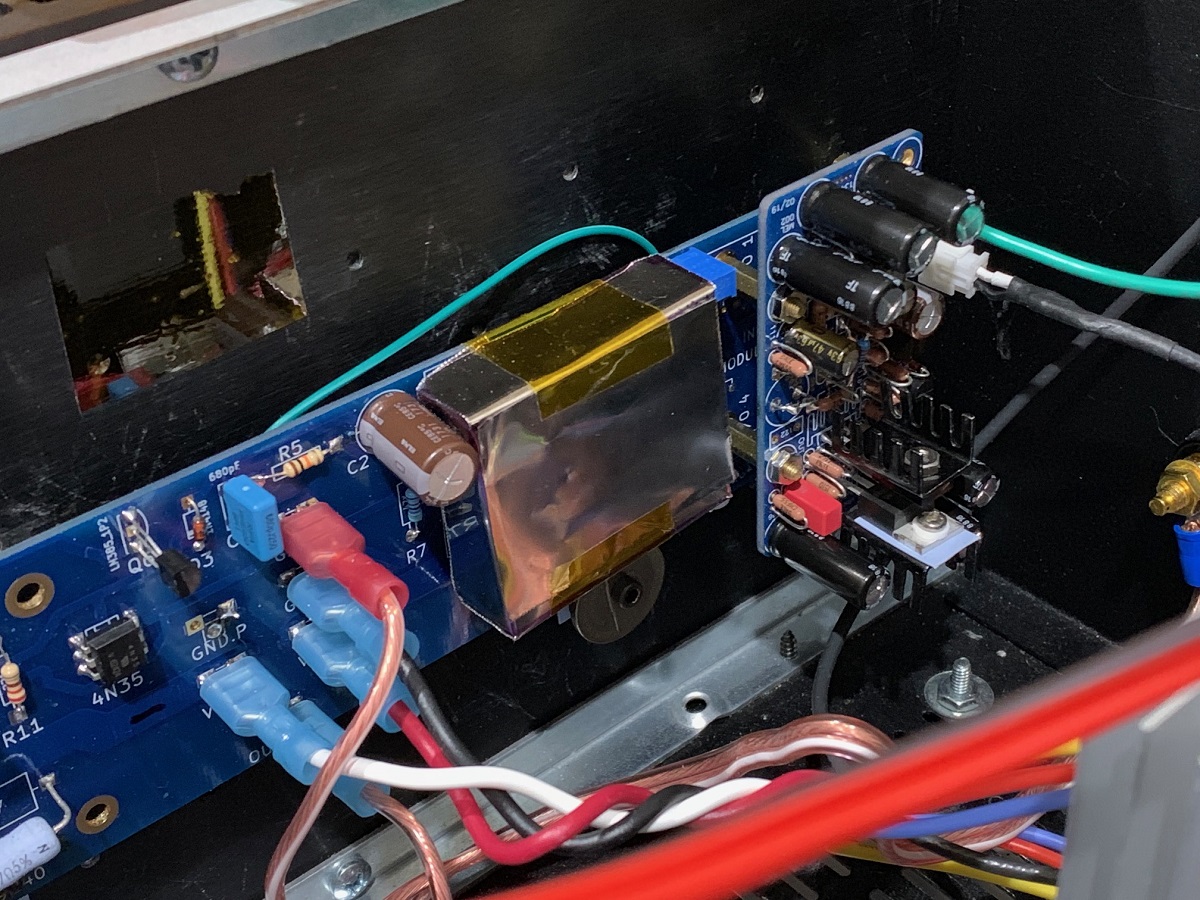
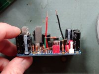
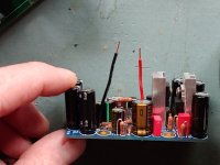
Here are some good clear close ups.
Thanks again,
-Josh
Attachments
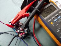
You are only getting 11mA (0.096v/8.2R) so something is off. Double check resistor values against the schematic.
Next step to debug is for you to use DVM probe and measure DC voltage at every major node on schematic. Mainly each pin of each transistor, output node, and voltage across resistor above LTP. Write those in red ink on the schematic at appropriate location. Take photo of that marked up schematic and post it. This will tell all and let us fix the issue.
Next step to debug is for you to use DVM probe and measure DC voltage at every major node on schematic. Mainly each pin of each transistor, output node, and voltage across resistor above LTP. Write those in red ink on the schematic at appropriate location. Take photo of that marked up schematic and post it. This will tell all and let us fix the issue.
You are only getting 11mA (0.096v/8.2R) so something is off. Double check resistor values against the schematic.
Next step to debug is for you to use DVM probe and measure DC voltage at every major node on schematic. Mainly each pin of each transistor, output node, and voltage across resistor above LTP. Write those in red ink on the schematic at appropriate location. Take photo of that marked up schematic and post it. This will tell all and let us fix the issue.
Will do. It will probably take a few days unless I can get some extra time in tomorrow.
I appreciate your help,
-Josh
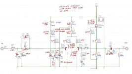
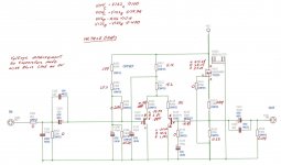
OK, I found some time.
All voltages are taken with respect to VEE, except voltage drops as marked. The voltages on the power input section are taken with respect to 0V.
On the board, R104 and R106 measure about half the rated resistance. I removed both resistors and measured them, both measure perfectly off the board.
The handful of the resistors not measured will not stabilize, mostly because of what looks like capacitor charging.
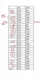
I have included the table I used for recording the resistor values before transferring them to the schematic.
Once again, I really appreciate the help,
-Josh
All voltages are taken with respect to VEE, except voltage drops as marked. The voltages on the power input section are taken with respect to 0V.
On the board, R104 and R106 measure about half the rated resistance. I removed both resistors and measured them, both measure perfectly off the board.
The handful of the resistors not measured will not stabilize, mostly because of what looks like capacitor charging.
I have included the table I used for recording the resistor values before transferring them to the schematic.
Once again, I really appreciate the help,
-Josh
Attachments
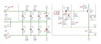
Thanks for going that. It would have been good if everything was measure vs 0v. What were measurements for V122 (KSA1381)?
Hi Josh,
You have about half the current flowing through V116, the VAS transistor. It should have an additional 1.5mA through the 100R resistor in the emitter, V116.
This problem tells me there is no connection between the collector V114 and base V112. Check there is continuity there, and then from emitter to the top of top of R116. OR, check again that R122 464R is connected across emitter to base of V122, there may be a break there too.
The LTP seems to be working quite OK, it is not the problem.
When you are trying to find issues, measure voltages across resistors as well so you can figure our currents, and always have your black probe on GROUND. That is much clearer to find issues. All you power supply rails/caps/resistors are just fine too.
Good luck!
Hugh
Last edited:
Thank you both for the replies.
I re-measured the voltages to the actives with reference to 0V.
I also checked the voltage drop across all resistors.
Attached is the schematic with the measurements.
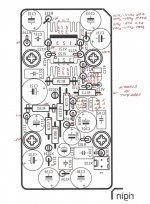
Also attached is a mirror image of the stuffing diagram with all the measurements recorded as I took them. I am dyslexic, so I use simple aides like this to make sure I am recording the right things.
@xrk971
Sorry, I forgot to add V122. The measurements from VEE are
E: 24.9
C: -25.24
B: 20.86
They are about the same measured from 0V, see attached pics.
@AKSA
I think I interpreted what you want correctly. There is no V112, so I took the measurements from V114 to V122
I really appreciate the help.
-Josh
I re-measured the voltages to the actives with reference to 0V.
I also checked the voltage drop across all resistors.
Attached is the schematic with the measurements.
Also attached is a mirror image of the stuffing diagram with all the measurements recorded as I took them. I am dyslexic, so I use simple aides like this to make sure I am recording the right things.
@xrk971
Sorry, I forgot to add V122. The measurements from VEE are
E: 24.9
C: -25.24
B: 20.86
They are about the same measured from 0V, see attached pics.
@AKSA
I think I interpreted what you want correctly. There is no V112, so I took the measurements from V114 to V122
I really appreciate the help.
-Josh
Attachments
Figured it out!
Will have to explain later, I am already late to be someplace - didn't want folks to waste any more time.
Thanks again!
-Josh
Will have to explain later, I am already late to be someplace - didn't want folks to waste any more time.
Thanks again!
-Josh
Let me guess, you had installed a PNP (KSA992) instead of NPN (KSC1845) for V122?
Good guess.
Being a dyslexic, I learned years ago how to prevent this type of error 🙂
A special smiley for anyone who can spot what is wrong with the pic...
If Mark Johnson contributed to this thread, he would probably invite me at this point to describe how I went about finding the problem, and what I did to fix it.
I found the problem by staring at the schematic for long periods of time trying to understand it fully. I read the questions I was asked very closely to try and divine why these questions are so important to answer.
After much consideration, I determined that everything was working more or less as it should, except V122. Given the base and emitter values, the -25V at the collector is not possible.
I know I installed the correct part because I read the part numbers, label the bags, and check them off a spreadsheet. I also download the data sheets for transistors to make sure the pinouts for my part actually correspond to the traces on the boards (learned this the hardway a while ago...).
Therefor I must have installed the transistor backwards...
once again, many thanks to all of you. I am smarter today than I was yesterday. I was able to find the problem because of your help.
-Josh
P.S.
My son and I sat down and had a first impression session with Melbourne last night.
Final judgement will have to wait for the MCU board for my DAC to arrive (10days and counting in customs), but we where both very impressed.
I am using the DAC in my NAD-758, which is pretty decent but not great.
My intuition says that the Alpha Big Boy will have be something really special to replace this set up.
One thing for sure though, it does have too much gain. Not sure if this is the substituted V122 I used or not.
Attachments
joshua43214,
Good to know that you've managed to identify the problem and get things sorted out. Also looks like you're smitten by the sound. 🙂
What speakers do you have in the current setup?
Good to know that you've managed to identify the problem and get things sorted out. Also looks like you're smitten by the sound. 🙂
What speakers do you have in the current setup?
Replacement DAC arrived yesterday, will report back after it has a chance to burn in a bit (the Allo DAC's do improve with time alot).
@zman01 I have 6Pi Cornerhorns from Pi Speakers. They have the upgraded B&C DE250 compression drivers installed, and I am waiting on the Acoustic Elegance TD125 w/ Apollo bass drivers. They nearly 5' tall and have a very low WAF, but they sound extraordinarily good, and a very sensitive. As expensive speakers go, they are also quite affordable. If you have tools and woodworking skills, you can make a pair at a very reasonable price.
I have a (very long) build thread I never got around to finishing on their forum detailing building the 2Pi towers, the 3Pi sub, and the 6Pi Cornerhorns.
AudioRoundTable.com: Pi Speakers >> Build Thread: 2Pi Towers, 6Pi Corner horns (and possibly a sub and center)
It goes into great detail on technique, and discussion of decisions. The build is nearly complete, and nothing important is missing.
So far, out of the box, the Melbourne sounds very nice in my M2x.
-Josh
- Home
- Group Buys
- Melbourne Daughterboard for M2X