IAIMH,
Great workmanship and build quality - very neat work! I also use these to drive 16ohm IEM's (KZ ZS-5's gen 2 and ZS-6) and they work superbly. The bass on those IEMs is pretty intense, like HT style deep. I also think they work very well with my OB-1's (55ohm). I have also listened to the Meze over ear wooden ones before (at a Head-Fi meet in Maryland a few years ago) - they sound great with this amp too.
Enjoy!
X
Hey X I finally got my pocket amp going. My dad has been wearing hearing aids all his life and this is the first time he has ever herd the sound of water and the ring of a bell. It has 2 MAX9814 amp chips and 2 5 band equalizer circuits part number BA3812L. All anolog with all silmic coupling capacitors. He calls it his golden ears. And they are dead silent, he was walking around at night and he was like i don't hear anything then he talked and he is like oh they are working. lol.
btw when are you getting more circuit boards in. I need another for backup?
Whats the part number for the headphone jacks? just wondering
Thanks potatopie
btw when are you getting more circuit boards in. I need another for backup?
Whats the part number for the headphone jacks? just wondering
Thanks potatopie
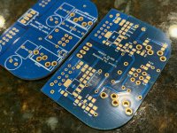
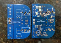
Great looking boards! Can't wait to build a few more with friends.
So, as a noob, I was bound to do something foolish at some point... and I did.
I could really use a bit of help troubleshooting. I had two perfectly functioning amps until I went to install them in the Altoids tins. I was in a bit of a rush, so you guessed it, I didn't properly cover the leads for the C3 caps. One or both sides grounded / shorted with the case. Pretty light show...
Amp Alpha - one working channel (Right)
Amp Beta - neither channel working
I am new to circuits, so after studying the schematic again, I went back through this thread and found a few issues where X and others have helped.
Physical observations - under 2.5x and 10x magnification - nothing on either amp board looks burnt. No bulges in caps, no discolored parts. For troubleshooting I used two freshly charged EBL 600mAH batteries measuring 8.14V each.
Here are the measurements I took on Alpha (right channel working)
MosFET Legs to Ground
1A Gate - 7.7V OK
2A Drain - 0V !
3A Source - 10.75V (Over goal of 6-8V)
1B Gate - 7.23V OK
2B - Drain - 0V !
3B - Source - 10.22V (Over goal of 6-8V)
Across R3
A - 7.72V & 8.6mA
B - 7.25V & 8.08mA
Here are the measurements I took on Beta (neither channel working)
MosFET Legs to Ground
1A Gate - 6.13V (Low to goal of 7-9V)
2A Drain - 0V !
3A Source - 9.23V (Over goal of 6-8V)
1B Gate - 7.08V (Low, but within range of 7-9V)
2B - Drain - 0V
3B - Source - 10.19V (Over goal of 6-8V)
Across R3
A - 6.25V & 6.99mA
B - 7.14V & 7.92mA
Where I am most confused is that in post #665 it is mentioned that I should have between 15 and 18V at pin 2. Both amps (all 4 pins) measure 0.
I haven't found any guidance on the web to check caps or the JFETs in situ.
Fortunately, I have a lot more parts coming, so I am willing to replace any components as needed.
Any guidance is appreciated.
If you measure voltage on Source pin 3 there must be some voltage on pin 2. Pin 2 is same as the tab or the exposed via holes around the tab. Try those.
10v at the source pin is too high and I can only imagine that you may have an incorrect resistor somewhere that is causing it. Or you have a very “hot” MOSFET. Please show some clear sharp closeup photos of your amps (SMT) side do we can check the resistors.
If you had a light show from the exposed C3 leads it is usually not any more than replacing C3. Electrolytic caps can get damaged from shorts. You might also try some alkaline batteries to make sure it’s not your EBLs that are blown. They measure well but the moment they are exposed to a short (the bad C3’s) they shut off to self protect.
Before that happens, they have charged up the output caps and that’s why you have a voltage at Source but not at Drain.
I think you may need to change C3. At worst you may need to change MOSFETs. If you measure resistance across D and S and it’s not in hundred Kohms but 1ohm to 20ohms, it’s dead.
Good luck.
Hi X -
Thank you very much for the response (particularly on a weekend).
I measured the resistance between the drain and source for all for MOSFETs. They all started at ~200ish ohms then climbed to over limit.
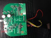
I double checked all resistor values, but additional eyes are always appreciated. I attached photos below. Getting all the resistors in focus is tricky, but I got shots where they should all be legible. If not, I can try again (there are some blurs).
Next step (unless guided otherwise,) is to replace the C3s. I need to wait until I get my parts order for the next builds. That should be Tues. I'm out, and did not order extras.
I checked the behavior of the drains (I measured between pin 2 and the vias) and still got 0 Volts. I swapped to a new set of EBLs just in case and also tried alkaline. The EBLs sometimes do take two "clicks" of the on switch to get them to go, but I read that was normal behavior. I still get over 10V at the source pins. I can check that again after replacing the C3s.
I've got a hot air gun on the way (I needed one anyway). So, if by chance I do need to replace the MOSFETs, I stand a better chance of not destroying the board in the process. The good news is that both amps were working flawlessly before I put them in the cases.
Pics below - Note I bent C1a and C1b back up and removed the Kapton tape for visibility along with double checking values.
Alpha -

Beta -

Thank you very much for the response (particularly on a weekend).
I measured the resistance between the drain and source for all for MOSFETs. They all started at ~200ish ohms then climbed to over limit.
I double checked all resistor values, but additional eyes are always appreciated. I attached photos below. Getting all the resistors in focus is tricky, but I got shots where they should all be legible. If not, I can try again (there are some blurs).
Next step (unless guided otherwise,) is to replace the C3s. I need to wait until I get my parts order for the next builds. That should be Tues. I'm out, and did not order extras.
I checked the behavior of the drains (I measured between pin 2 and the vias) and still got 0 Volts. I swapped to a new set of EBLs just in case and also tried alkaline. The EBLs sometimes do take two "clicks" of the on switch to get them to go, but I read that was normal behavior. I still get over 10V at the source pins. I can check that again after replacing the C3s.
I've got a hot air gun on the way (I needed one anyway). So, if by chance I do need to replace the MOSFETs, I stand a better chance of not destroying the board in the process. The good news is that both amps were working flawlessly before I put them in the cases.
Pics below - Note I bent C1a and C1b back up and removed the Kapton tape for visibility along with double checking values.
Alpha -
Beta -
Your resistors look good. You may have blown your on/off switch portion of your pot. Try soldering a jumper across the power pins on pot to bypass the switch. That might be why you have 0v at the Drain.
Thank you for double-checking the resistors. If the on/off switch is blown, then why would the LED turn on and off? Serious question. I reviewed the schematic, but being a noob...
Based on your thoughts, I tried measuring the resistance between each of the pot's pins in a potentially meaningful way to see if the on/off was functioning, but I came up with nothing I could make sense with.
Again, apologies for naive questions. If I run a jumper between the two points in yellow (leaving the middle pins alone) does that accomplish what you're recommending? Are those the "power pins"? By looking at the schematic and the PCB layout, I think that would set it to "always on" and bypass the pot, but I'm not 100% sure.

X - I also realized that I may not understand the layout of the board as well as I should. Just so I'm not running you around in circles and wasting your time...
The points in RED are where I was measuring the voltage between pin 2 and ground. When I look at the board itself vs. the trace diagram, Pin 2, Pin 4 (the large back pin) and the vias all seem to share the same copper pad.
Have I measured pin 2 completely incorrectly? I can't understand how I'd get a voltage the way I measured it if my observation re: the board construction is accurate.
I measured pins 1 and 3 similarly, with one probe on the "leg" and one in the via.
I'd hate for you to waste effort if my measurements were not taken properly.
As always, with thanks!

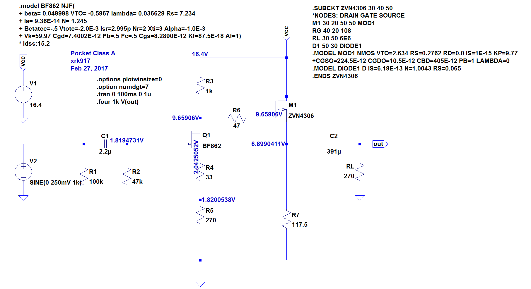
Below is from post #665
"On MOSFET just these 3 measures (relative to GND) will tell you if amp is working:
1. D (pin 2 or tab) says you have the main power applied to the amp (15 to 18v)
2. G (pin 1) says the gate voltage set by JFET is working (if off then check volts across R3) (7v to 9v)
3. S (pin 3) says bias current is flowing through resistor array and you have Class A action (6v to 8v)"
The points in RED are where I was measuring the voltage between pin 2 and ground. When I look at the board itself vs. the trace diagram, Pin 2, Pin 4 (the large back pin) and the vias all seem to share the same copper pad.
Have I measured pin 2 completely incorrectly? I can't understand how I'd get a voltage the way I measured it if my observation re: the board construction is accurate.
I measured pins 1 and 3 similarly, with one probe on the "leg" and one in the via.
I'd hate for you to waste effort if my measurements were not taken properly.
As always, with thanks!
Below is from post #665
"On MOSFET just these 3 measures (relative to GND) will tell you if amp is working:
1. D (pin 2 or tab) says you have the main power applied to the amp (15 to 18v)
2. G (pin 1) says the gate voltage set by JFET is working (if off then check volts across R3) (7v to 9v)
3. S (pin 3) says bias current is flowing through resistor array and you have Class A action (6v to 8v)"
Voltage should always be measured relative to ground. Ground is the pin on battery connector on opposite end of positive or the pin closest to edge on LED.
Well, don't I feel silly.
 I won't make that error again. My apologies. Once again, thank you for your patience.
Here are the correct measurements.
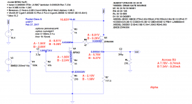
Alpha - Right channel working
Legs to Ground
1A Gate - 8.15V - OK
2A Drain - 15.80V - OK
3A Source - 5.08V - Below goal of 6-8V
1B Gate - 8.60V - OK
2B - Drain - 15.80V - OK
3B - Source - 5.61V - Below goal of 6-8V
Across R3
A - 7.69V & 8.49mA
B - 7.25V & 7.99mA
Beta - Neither channel working
Legs to Ground
1A Gate - 9.73V - Higher than goal of 7-9V
2A Drain - 15.80V - OK
3A Source - 6.62V - OK
1B Gate - 8.78V - OK
2B - Drain - 15.80V - OK
3B - Source -5.65V - Below goal of 6-8V
Across R3
A - 6.1V & 6.83mA
B - 7.00V & 7.75mA
Your measurements show that the amp is working fine. Compare the voltages to the simulation at the various points. They are not far off - it should play music. Do you have the Input jack and output jacks reversed? Input is on left and output is on right side when SMT side is up. I have made that mistake. No sound.
Your measurements show that the amp is working fine. Compare the voltages to the simulation at the various points. They are not far off - it should play music. Do you have the Input jack and output jacks reversed? Input is on left and output is on right side when SMT side is up. I have made that mistake. No sound.
Hi X - You have incredible patience and a skill for teaching. I can't thank you enough. I had that printed out. At least I'm on the right path. I've measured all points on one of the amps (the Beta amp that had one channel working). As I was fiddling with the amp, the channel came in and out. I am going to re-check all joints, physical legs of caps etc. before troubling you further and taking more of your time. As a reference though, here are the measurements.
For the next batch of "amps with friends", I clearly need to try and learn your sorting and biasing process. The two channels are not electrically matched to your expectation. My goal was music - then tweak and learn further.
Pausing for now, and will report back tomorrow when I'm less on edge and have a bit more time. Such a silly mistake to goof up two functioning amps by hurrying.
If I make it to see family in the DC area, and you're up for it - at the very least a nice meal is on me.

With thanks!

Edited to Add - I forgot to add the point between R4 and R5 to the picture. A = 2.08V B=1.95V
Last edited:
You are welcome to stop by lab for a visit if in DC area. If you want to match FETs - use one of your boards all populated with resistors and caps but leave the FETs unpopulated. Connect amp to power - preferably Alkaline batteries so they don’t shut down. Solder some small wires across R3 and connect DVM. Take a JFET and place on pads and use a pencil with eraser to apply pressure to JFET and measure the voltage across R3. Record that with JFET. Do this for maybe 12 to 20 and you should have a pair that matches within 2%. Use those. Now install those matched JFETs and solder some small test leads across the the 4x 470R source resistors and connect DVM. Do same thing with MOSFETs. Record voltages for about a dozen and pick two that are within 5% or better. If you have lots of them aim for 2% or 1%. When you buy Uber hand matched JFETs from me they are matched to 1% or better. Takes a lot of stock to do that though. Now when you build them up, both channels will have almost the same bias current and same sensitivity.
X - Thank you for the kind offer. I hope to take you up on it.
Noted re: the process. I have it in my build notes. When I get the next set of boards, I'll dedicate one for matching and then use it for a build after all the parts have been measured. Related to that, is it okay to simply swap R4 for unmatched MOSFETs? i.e. have one value for A and another for B?
On to the good news. I now have two perfectly functioning amps. Two things (at least I think) contributed to the situation.
1) I don't know if it's related to the situation or not, but one channel on my test earbuds was out. Perhaps it got smoked during the light show. They were disposable buds you get on an airplane. If it's not related, then it's an odd coincidence. After the re-flow and visual check on Beta, it still had a channel out. On a fluke, I swapped to another set of buds - MUSIC!. Done.
2) On Alpha - I tried the new buds and got one channel. Progress. I did the same reflow, cleanup and visual check. There is a solder bridge between C4 and C5. On the side of the pads it was on, it should not affect the circuit. However, after the reflows and checks, and rechecks, it now functions perfectly again. I truly have no idea what caused the channel to go out. For anyone's interest - the measurements are attached below. Note - batteries were charged over night.
Again, I can't thank you enough.
The twins. I think it's time to do some other tins.
Attachments
IAIMH:
Congratulations! Based on your measurements, I knew that the amp was still good and should have made music. You may have had a solder bridge form or a cold solder joint break when the arcing happened. You can adjust the R4's individually - make them higher value to increase the bias current across the MOSFET. Change them in small amounts. Note that if they are too far apart, their harmonic profile balance between H2 and H3 will not be the same, but you may or may not hear that. You don't want to go over 57ohm. You can use a 57ohm and parallel (on top) another resisitor that is large like 470ohms etc to slowly bring the parallel resistance down to match,
Enjoy your amps!
- Home
- Group Buys
- xrk971 Pocket Class A Headamp GB