I just implemented the above diagram and it works well. I added a CRCRC after the cap Mx and before the amp. It can still play music even when charging via USB as shown in photo below. My charger module has just one connection for the battery and the output. The battery itself has the smart protection circuit built in. I am running at a full 18v Vcc to see how well this can play low impedance phones. I have also retrofitted the new resistor values for low impedance. It turns out adding a parallel 4k7 chip resistor to 1k makes it an 820R so you don't need to uninstall. I did swap out the 270R R5 for 220R though.
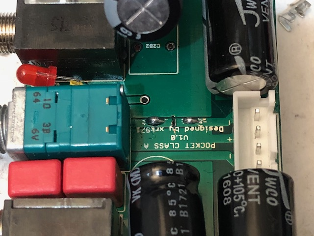
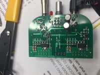
Here is closeup of the trace cut and the new solder pads added to go to battery and cap Mx input:
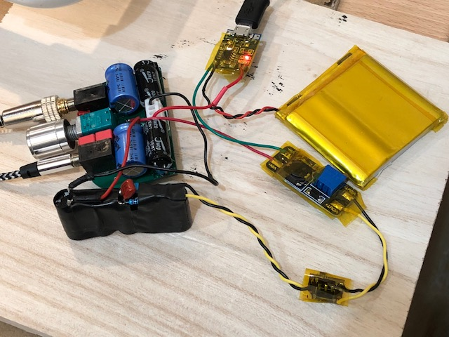
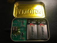
Here is testing the flat-pack for functionality before putting it in the case:
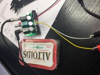
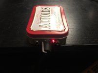
Here is the finished amp undergoing a charge and playing music at same time:
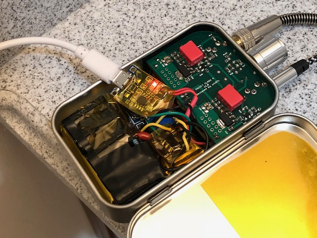
I don't mind opening the lid to charge. Having the power switch function to turn on/off the cap Mx is a nice touch.
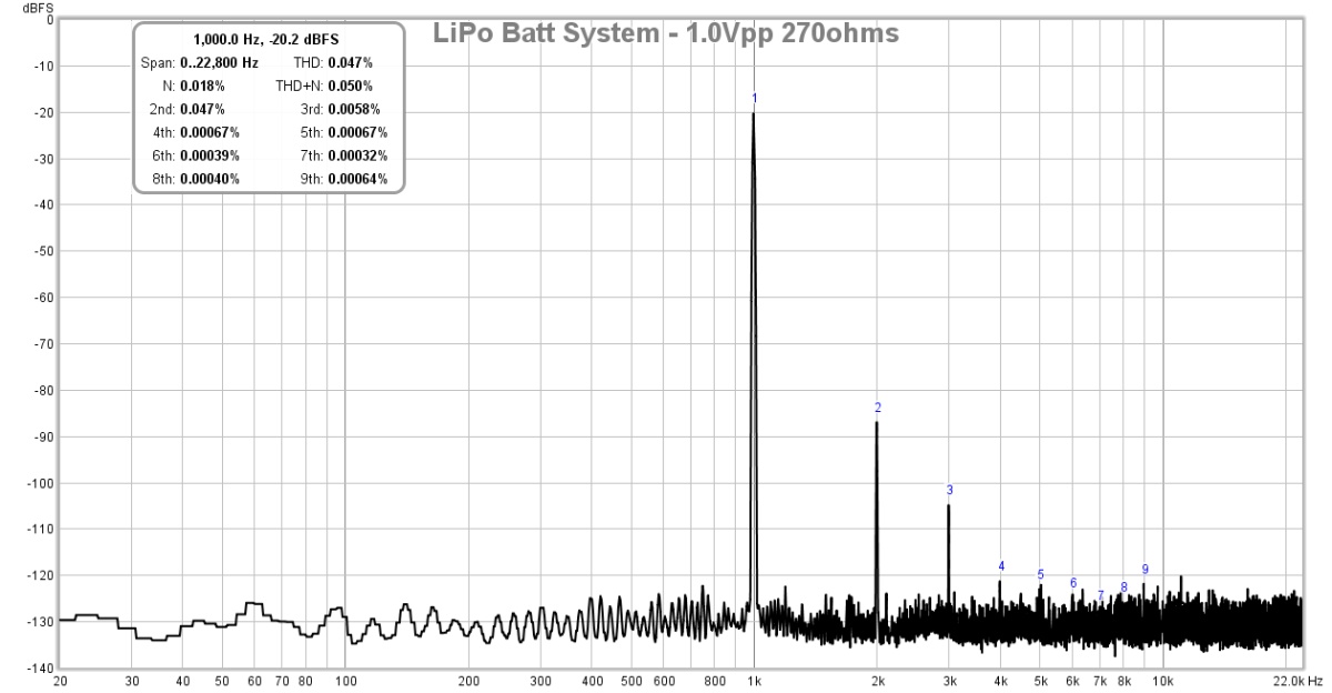
Here is FFT for 1Vpp itno 270ohms (0.05% THD all H2 and H3):
Here is FFT for driving 50ohm load (0.24% THD, and about same harmonic profile)
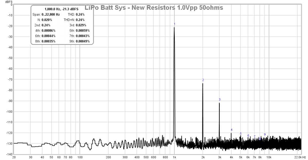
The DC step up and CRCRC combo is doing a great job with keeping noise to a minimum level, flat at -130dB.
Can someone point to a link to find a lipo battery pack thats used here? Many thanks
I think it was a 52mm x 51mm x 7.8mm thick 2600mAhr battery.
3.7V 2600mAh Li-Polymer lipo Battery For Power Bank mobile phone PDA GPS 785251 | eBay
3.7V 2600mAh Li-Polymer lipo Battery For Power Bank mobile phone PDA GPS 785251 | eBay
This amp topology is now also available as an add-on daughterboard to the Aksa Lender preamp/headphone amp. But gives you choice of BF862, 2SK209, or 2SK170 for the input JFET.
AKSA's Lender Preamp with 40Vpp Ouput GB
AKSA's Lender Preamp with 40Vpp Ouput GB
Latest NHB BOM for PCA to drive both low and high impedance headphones.
Code:
PCA BOM for low (32ohms) and (600ohm) high impedance cans
July 16, 2019

Check	Label on Board	Qnty	Value	Notes
	R1	2	100k	0805 1/8W Metal Oxide Film 1%
	R2	2	47k	0805 1/8W Metal Oxide Film 1%
	R3	2	1k	0805 1/8W Metal Oxide Film 1%
	R4	2	47R	0805 1/8W Metal Oxide Film 1% (nominal is 47R, increase for higher bias)
	R5	2	270R	0805 1/8W Metal Oxide Film 1%
	R6	2	47R	0805 1/8W Metal Oxide Film 1%
	R7(1-4)	8	470R	0805 1/8W Metal Oxide Film 1%
	RLED	1	12k	0805 1/8W Metal Thin Film 5%
	RL	2	270R	0805 1/8W Metal Oxide Film 1%
	C1_A/B	2	10uF 35V	Elna Silmic II (silk insulator),  -ve terminal faces front edge
	C2_A1/B1	2	1000uF 16V	Panasonic OSCON SEPF
	C2_A2/B2	2	1000uF 16V	Panasonic OSCON SEPF
	C3	2	2200uF 16V	Nichicon, use shrinktube on legs
	C4A/B	4	100nF X7R 	0805 X7R 100v
	Q1	2	BF862	N-junction JFET (NXP)
	M1	2	ZVN4306	N-ch MOSFET (ZETEX/Diodes Inc) or ZXMN10A08GTA
	Input	1	3.5mm stereo jack	Switchcraft
	Output	1	3.5mm stereo jack	Switchcraft
	Pot	1	10k linear w/ power	Alps Rk09 with 6mm shaft with flat
	LED	2	3mm	blue and white included, use shrinktube on +ve leg
	BATT	1	JST 4-pin 0.1in pitch
	Vol Knob	1	6mm shaft with flat	Machined Aluminum with plastic core
PCB 1 v1.0 1,6mm 2-layer PCBWhat happened to the revised low bias values from your earlier post a few months ago?
Looks like these recent ones reverted close to the original BOM values?
Looks like these recent ones reverted close to the original BOM values?
Latest NHB BOM for PCA to drive both low and high impedance headphones.
Code:PCA BOM for low (32ohms) and (600ohm) high impedance cans July 16, 2019 Check Label on Board Qnty Value Notes R1 2 100k 0805 1/8W Metal Oxide Film 1% R2 2 47k 0805 1/8W Metal Oxide Film 1% R3 2 1k 0805 1/8W Metal Oxide Film 1% R4 2 47R 0805 1/8W Metal Oxide Film 1% (nominal is 47R, increase for higher bias) R5 2 270R 0805 1/8W Metal Oxide Film 1% R6 2 47R 0805 1/8W Metal Oxide Film 1% R7(1-4) 8 470R 0805 1/8W Metal Oxide Film 1% RLED 1 12k 0805 1/8W Metal Thin Film 5% RL 2 270R 0805 1/8W Metal Oxide Film 1% C1_A/B 2 10uF 35V Elna Silmic II (silk insulator), -ve terminal faces front edge C2_A1/B1 2 1000uF 16V Panasonic OSCON SEPF C2_A2/B2 2 1000uF 16V Panasonic OSCON SEPF C3 2 2200uF 16V Nichicon, use shrinktube on legs C4A/B 4 100nF X7R 0805 X7R 100v Q1 2 BF862 N-junction JFET (NXP) M1 2 ZVN4306 N-ch MOSFET (ZETEX/Diodes Inc) or ZXMN10A08GTA Input 1 3.5mm stereo jack Switchcraft Output 1 3.5mm stereo jack Switchcraft Pot 1 10k linear w/ power Alps Rk09 with 6mm shaft with flat LED 2 3mm blue and white included, use shrinktube on +ve leg BATT 1 JST 4-pin 0.1in pitch Vol Knob 1 6mm shaft with flat Machined Aluminum with plastic core PCB 1 v1.0 1,6mm 2-layer PCB
Decrease R4 a little bit to lower the bias current. You are at 6.9v / 117.5ohms is 58mA bias current. Not too hot actually. I have run as high as 70mA. But if you want to run at 5.8v which is 50mA that’s fine too. In order to reduce the resistance of R4 in small increments, parallel a large value like 1k or 820R etc with the R4 nominal value of 47R. It will take trial and error.
Alternatively, you can use matched FETs and the bias current will be the same.
Alternatively, you can use matched FETs and the bias current will be the same.
Hi xrk971 I lowered r4 to 35 ohms got it down to 6 volts and now both run at about 54-56 degrees celsius after about 1 hour. One channel sounds like really open and lively. the other channel sounds dull with little bass and little treble and is quite a bit lower volume? missmatched transistors? Bad cap? I went ahead and ordered a matched set from you today. What idss range of transistors is your headphone amp designed for? Ive built a Nelson Pass F5 amp kit from diy audio store 2 years ago
and its input fets were designed for 6-12 ma idss. Just wondering.
Thanks
Benjamin and btw whats your name?
and its input fets were designed for 6-12 ma idss. Just wondering.
Thanks
Benjamin and btw whats your name?
Hi Potatopie,
Thanks for ordering the matched FETs. I match them in-situ (with similar operating DC setpoints - to get the true actual current matched). Typically they will the provide the MOSFETs with 50mA (low), 60mA (med) to 70mA (high) bias current range. You can select low, medium, or high. High will let you drive lower impedance headphones. I would guess actual Idss to be on 10mA to 15mA range.
As to why one channel now sounds weak and distorted after the resistors mod? Might be that you have a cold solder joint or the JFET or MOSFET may be going bad, or your batteries are dead. It requires at least 15v from the two 9v to sound decent and undistorted. Try new batteries. For this reason using rechargeable Li-ion batteries makes sense. You can’t get more than 2.5hra out of alkaline cells but 4-5hrs from 600mAhr 9v Li-ion cells.
Cheers,
X
Last edited:
xrk971 I'm using 21700 5 amp lithium batteries and the amp is running at 16.45v after 1 hour of use. and it was sounding like that before the resistor mod. Ive also upgraded the 2200uf 16 volt caps to 10,000 hr 2200uf 25v low esr 12.5 by 25mm caps. not using the power plug on amp. I'm using the amp for my dad he is hard of hearing and using 32 ohms in the ear speakers balanced armature. also I added silmic bypass caps on the output caps too 10uf. I ordered a bunch from mouser. hopefully its just the transistors. what is the safe operating temp of output transistors?
Thanks
Benjamin
Thanks
Benjamin
I finally built my PCA this morning. It took me a while to get BF862s, and then I went on vacation. X - I can't thank you enough for answering all my questions and posting the updated BOM to the forum.
I need to freshen my breath a bit to get rid of the mints, wire up the batteries (Running off two lab supplies for the moment), and punch the case.
I think it sounds great with a set of Meze Classics. I'm sure the lab supplies aren't ideal, but if it sounds this good in this situation, then I know I'll be thrilled with batteries.
As a relatively new builder, I found the most challenging aspect of the build to be the physical positioning and lead bending for the larger caps. Odd, I know. For the next build, I may try a hot plate, heat gun, or some other method for the SMD soldering, but for one-offs, I don't mind hand soldering. Fired up with great tunes in both channels on the first shot. Excellent thread to learn the aspects of the build! I read it end to end. Thanks to X and all those that contributed. It makes things much easier for noobs. A few glamor shots attached. I'll post again after I get the batts hooked up tomorrow and get the case punched etc.
Attachments
Last edited:
")
X - Love that idea. The boards are fantastic as-is, but any tweaks will always help. There are a few part spacings that are a tad tight for hand soldering (couldn't fit my tweezers between the parts), but seriously fantastic boards.
Thanks to X and the Zman for the kind words.
Listened a bit with the Meze Classics. Then, since this is for on the go, I tried a few sets of IEMs (16 ohm). They sound phenomenal. No issues at all with the lower impedance phones which is what I needed this for. Built using the same components in the BoM most recently posted.
Finished pics. Rechargeable batts coming later today, but I couldn't resist.
Attachments
- Home
- Group Buys
- xrk971 Pocket Class A Headamp GB