Hi XRK,
Not sure if this has been mentioned before in this thread, lost the will to live after 52 pages ! 🙄
A friend said that as its a Class A amp and will run hot and did notice in one photo using your pcb that the 4306s had little heatsinks stuck on to them.
I will doing my own board ( am in the UK) so wondered if I need to take any extra measures to aid heat dissipation ?
Thanks
It gets warm, but not hot. About 8v at 0.060amp 0.5w dissipation and as designed there is heatsink from the tab to the PCB copper planes with vias. So between the load resistors and MOSFETs about 2w total heat output. Put a layer of Kapton tape on the inside bottom panel and top lid to increase emissivity of bare metal from 0.2 to 0.9. That helps to keep it cool. No one has had a thermal issue thus far. Probably over 200 units out there working thus far no problems with heat. You don’t need the little heatainks. I don’t use any.
Hey Stellar - sorry I haven't been getting email notifications on this tread for whatever reason, thought it had gone quiet. I still had to cut the trace, but instead of soldering to the trace (worried it may cause the trace to lift later on) I used the vias/header hole and the pot leg instead
I haven't tried, but I think keeping the header for power would still be possible? If you wanted to do what I did and stuff the capmx between the power & output caps you might have to use thinner gauge wires in that case.
I haven't tried, but I think keeping the header for power would still be possible? If you wanted to do what I did and stuff the capmx between the power & output caps you might have to use thinner gauge wires in that case.
YOB, did you manage to wire in the CapMX without cutting a trace? Looking at this photo of your work. Looks like you are going between a connector header hole and a pin from the switch in the pot? Seems easier!
Below is how Raptor suggested connecting it in post 1178 (red lines are cuts). He also said that he had to remove the header for some reason. Is that really necessary?
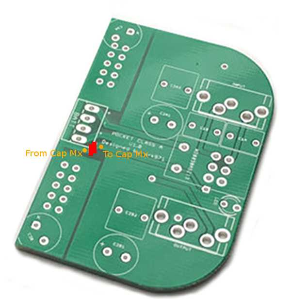
Maybe adding the additional boards require the more difficult hookup? Sorry I have to lean on you all here but as you know my grasp of circuitry is zilch. I don't want to screw anything up...
Last edited:
I’m playing with a revised resistor network that should give better performance all around. It will lower 3rd harmonic to -20dB below 2nd and allow lower distortion when driving lower impedance loads while maintaining same profile for 250ohms loads vs 50ohms (just overall rise in THD when driving 50ohm load). Initial tests are very encouraging and I will share new values and test results soon for anyone wishing to try. Probably best to get a second board and make a “low impedance” amp. Or you can desolder some SMT’s chip resistors and reinstall with new values.
Summary of changes here:
R3 = 820R
R4 = 47R
R5 = 220R
R6 = 1R
That’s it!
Summary of changes here:
R3 = 820R
R4 = 47R
R5 = 220R
R6 = 1R
That’s it!
Last edited:
I need a new pair of glasses 🙁. The resistor value for resp. R5 and RL would be 220Ohm (instead of 200Ohm) and 330Ohm. Would this still be ok?
Either 220R or 200R works well. I would have used 200R but it’s not a common value. I have tested 220R and it works fine. RL can be anything even 1k is fine. Just not too low as it pulls overall impedance down.
I will post FFTs as soon as I get a chance.
I will post FFTs as soon as I get a chance.
Last edited:
Happy new year X and thanks new resistor network tweak.
Happy New Year to you Byrtt! 15 minutes ago I guess.

Yes thanks we just entered 2018 here so... and in Australia they entered many hours ago and are probably gone to bed or possible very drunk 😀
and in Australia they entered many hours ago and are probably gone to bed or possible very drunk 😀Happy New Year to you all.
YOB, thanks for your reply about trace cutting. Your photo makes more sense now.
It's currently 3 degrees Farenheit in my shop, so no soldering tonight, but I can still doodle indoors...
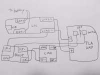
I am trying to draw a wiring diagram for connecting all four boards per the RaptorLightning mod, based on the above quote from post 1239.
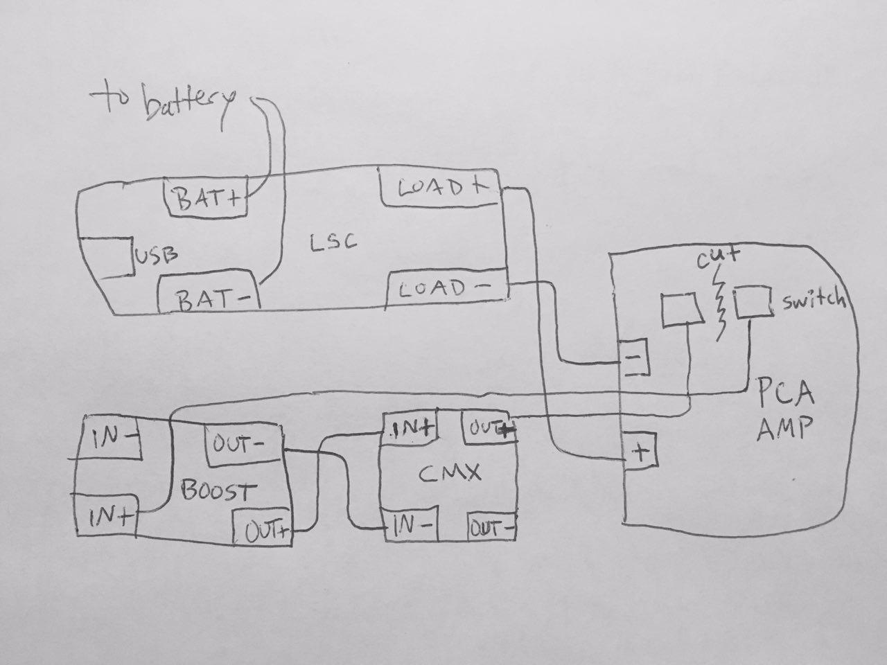
I am almost certain it ain't quite right 🙂 Please, can I get some help? Should something be connected to BOOST IN (-)? Any other mistakes? I left CMX OUT (-) disconnected because that's how it looked in the original photo of post 1169--even though that was before Raptor changed the layout.
YOB, thanks for your reply about trace cutting. Your photo makes more sense now.
It's currently 3 degrees Farenheit in my shop, so no soldering tonight, but I can still doodle indoors...
Battery/USB -> LSC Board -> Battery Terminals on PCA -> Trace Cut -> Boost Converter -> Cap Mx -> Back to other side of the trace cut and off to the PCA circuit.
I am trying to draw a wiring diagram for connecting all four boards per the RaptorLightning mod, based on the above quote from post 1239.
I am almost certain it ain't quite right 🙂 Please, can I get some help? Should something be connected to BOOST IN (-)? Any other mistakes? I left CMX OUT (-) disconnected because that's how it looked in the original photo of post 1169--even though that was before Raptor changed the layout.
Attachments
Last edited:
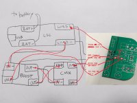
I think the only thing is in- of the boost should be connected to load- from the load share or -ve on the pca board (all the same). Cmx doesn't need out- connected because all the -ves are the same - you've already made the -ve connection from load share => pca so don't need another one (but won't hurt if you do)
I think the only thing is in- of the boost should be connected to load- from the load share or -ve on the pca board (all the same). Cmx doesn't need out- connected because all the -ves are the same - you've already made the -ve connection from load share => pca so don't need another one (but won't hurt if you do)
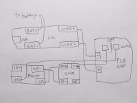
Like this?
Attachments
Is there any reason not to star ground?
Appears that the signals labeled as "-" are really ground on that board. Not sure about the boost board, but I'd be surprised if it had isolated grounds.
Appears that the signals labeled as "-" are really ground on that board. Not sure about the boost board, but I'd be surprised if it had isolated grounds.
Ground loops are not an issue in a small enclosed amp like this where convenience of wiring is important. If a star ground was adopted it would not be practical to tie all wires to the negative pin of the power connector - to small of a tie point.

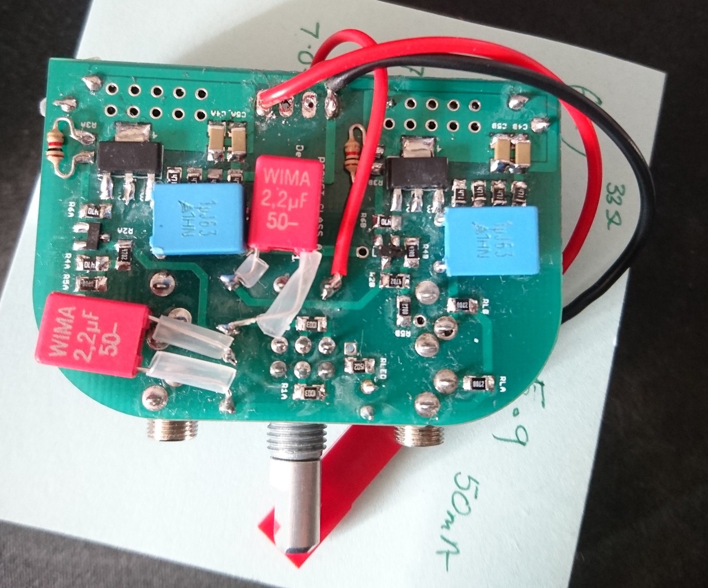
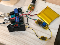
I just implemented the above diagram and it works well. I added a CRCRC after the cap Mx and before the amp. It can still play music even when charging via USB as shown in photo below. My charger module has just one connection for the battery and the output. The battery itself has the smart protection circuit built in. I am running at a full 18v Vcc to see how well this can play low impedance phones. I have also retrofitted the new resistor values for low impedance. It turns out adding a parallel 4k7 chip resistor to 1k makes it an 820R so you don't need to uninstall. I did swap out the 270R R5 for 220R though.
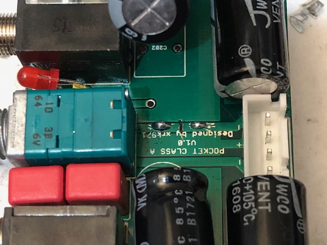
Here is closeup of the trace cut and the new solder pads added to go to battery and cap Mx input:
Here is testing the flat-pack for functionality before putting it in the case:

Here is the finished amp undergoing a charge and playing music at same time:
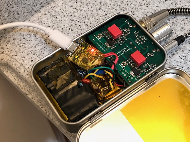
I don't mind opening the lid to charge. Having the power switch function to turn on/off the cap Mx is a nice touch.
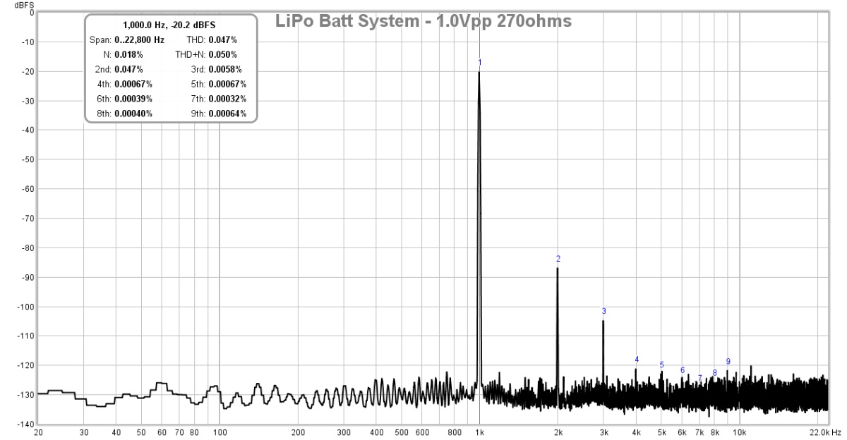
Here is FFT for 1Vpp itno 270ohms (0.05% THD all H2 and H3):
Here is FFT for driving 50ohm load (0.24% THD, and about same harmonic profile)
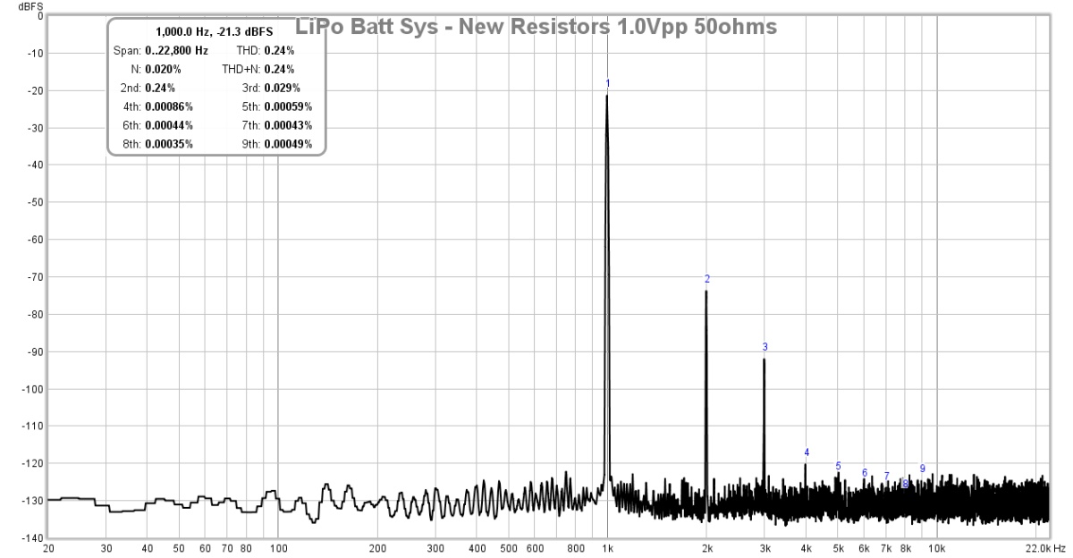
The DC step up and CRCRC combo is doing a great job with keeping noise to a minimum level, flat at -130dB.
Here is closeup of the trace cut and the new solder pads added to go to battery and cap Mx input:
Here is testing the flat-pack for functionality before putting it in the case:
Here is the finished amp undergoing a charge and playing music at same time:
I don't mind opening the lid to charge. Having the power switch function to turn on/off the cap Mx is a nice touch.
Here is FFT for 1Vpp itno 270ohms (0.05% THD all H2 and H3):
Here is FFT for driving 50ohm load (0.24% THD, and about same harmonic profile)
The DC step up and CRCRC combo is doing a great job with keeping noise to a minimum level, flat at -130dB.
Attachments


Last edited:
Listening to the new LiPo battery and upgraded resistor rig now. One very welcome and pleasant new feature with the cap Mx is that there is zero turn on/off pop. None! Absolutely silent even with 106dB IEMs plugged in. Also, cannot hear any noise with IEMs.
- Home
- Group Buys
- xrk971 Pocket Class A Headamp GB