wiring scheme maya
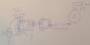
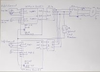
Hi Tibi, I have a question on the grounding setup of Maya. See schemes attached. I have a balanced Maya coupled to two alpha 24 AMB audio line amp's (I am building a preamp). In my drawing you only see one Maya board and one A24. Both A24's are fed by one PSU with -10V, G, and +10V.
Now my question relates to the grounding set up that is given in your Maya wiring drawing, see your scheme. It says that if the amplifiers (is this case the A24's) have one ground power (which is true in my case), I have to connect the PGND to the 'PSU G input' of the A24's. Do I understand it correctly? If so, What resistances do I have to use at R35 and R34?
I use a ground loop breaker between the signal ground (inputs) and the chassis (see my drawing). All boards are in the same chassis as my transformers.
Attachments
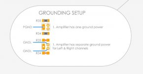
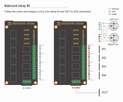
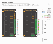
There are two ways for Maya balanced operation.
One is that you use one board for one channel (drawing setup#1), second is to combine input L&R on one board (drawing setup#2).
The one I recommend is setup#1 and for this is better to have R34 and R35 in place.
I see no reason for the ground connection you made at the output. In fact this will make huge loops and you end up with lot of noise.
To avoid ground loops use a star connection. Do not pass ground in series from one module to another. Make a star connection as close to small input signal, or connect input ground to enclosure and use enclosure as main ground point.
Regards,
Tibi
Attachments
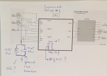
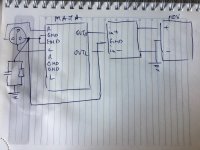
Thanks Tibi. I was not clear about the input side in my previous drawing, I drew RCA inputs in one board which is not reflecting what I do. Pls see the new wiring scheme attached, it was given earlier in this thread, this is how I do it too. Shown in the scheme is one channel. I use your Balanced setup #1.
Can I ask you some further questions:
Which parts do I need for R35 and R34, do you have a link? To be sure, I need to add them to both boards, OK?
And where do I connect the two PGND's on the Maya pcb's to?
I added a ground loop breaker (R = 10 Ohm/5W, C = 0.1 uF/250V) at the point where in the scheme you connect the star input grounds to the enclosure (ground). Is that OK? I have two ground loop breakers, one for left channel inputs ground, one for the right channel, OK?
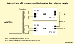
I use 2 Alpha 24 line amps powered by a Sigma25/Sigma26 PSU +10V, G, _10V (see second scheme). Do I need to connect power ground (G) to the enclosure (ground) or somewhere else?
Thanks! Pieter
Can I ask you some further questions:
Which parts do I need for R35 and R34, do you have a link? To be sure, I need to add them to both boards, OK?
And where do I connect the two PGND's on the Maya pcb's to?
I added a ground loop breaker (R = 10 Ohm/5W, C = 0.1 uF/250V) at the point where in the scheme you connect the star input grounds to the enclosure (ground). Is that OK? I have two ground loop breakers, one for left channel inputs ground, one for the right channel, OK?
I use 2 Alpha 24 line amps powered by a Sigma25/Sigma26 PSU +10V, G, _10V (see second scheme). Do I need to connect power ground (G) to the enclosure (ground) or somewhere else?
Thanks! Pieter
Attachments
OK, I see you already connected L and R plane ground at the input. That is sufficient.
No need for R34=R35=0 ohm
That "ground breaker" must go to amplifier power ground, not chassis.
You do not need to connect next stage ground to Maya, instead this must be connected at ground star point. In your case XLR connectors.
Regards,
Tibi
No need for R34=R35=0 ohm
That "ground breaker" must go to amplifier power ground, not chassis.
You do not need to connect next stage ground to Maya, instead this must be connected at ground star point. In your case XLR connectors.
Regards,
Tibi
Thanks for your replies!
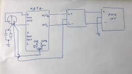
Based on your replies, can you have a look at my new scheme? Now, I did not connect the ground of the inputs together. Because, if I understand you well, instead of connecting all L and R plane ground at the signal input connectors, we can also solder a 0 ohms wire at R34 and R35 at both Maya PCB's, do I understand that correctly, or am I wrong?
Next, I have to connect PGND of both Maya PCB's via one ground loop breaker to the power ground of my line stage amps, see scheme. Is that correct?
Then, there is no connection at all between signal input ground or power ground to the enclosure/chassis? Is that correct?
All my input and output connectors (RCA and XLR) are isolated from the enclosure. My aluminum enclosure/chassis is connected to the ground from the wall power connector.
Attachments
You are welcome !
As you have drawn, you have several ground loops.
First at Maya. if you connect left and right signal ground together and in the same time mount R34=R35=0ohm, than you have ground loops.
Keep all ground connections in a star.
Regards,
Tibi
As you have drawn, you have several ground loops.
First at Maya. if you connect left and right signal ground together and in the same time mount R34=R35=0ohm, than you have ground loops.
Keep all ground connections in a star.
Regards,
Tibi
Attachments
Hi Tibi, I just got a new phone and restored a full backup from the old one. Still when opening Maya there is a message saying “Unable to install, the app is not available on the appvalley AppStore”. How to resolve this?
I'm facing the same issue...If you find any solution then let me know....
regards,
pdu2019
Maya documentation Dropbox - MayaDocumentation.zip - Simplify your life
Last GB info Maya R2R Advanced Volume controller
https://www.diyaudio.com/forums/gro...ced-2r-logarithmic-ladded.html?highlight=maya
Latest Android app https://www.diyaudio.com/forums/att...nced-volume-controller-maya_ble_april2020-zip
Android source MIT Inventor https://www.diyaudio.com/forums/att...a-r2r-advanced-volume-controller-maya_ble-zip
Latest Maya firmware https://www.diyaudio.com/forums/att...nced-volume-controller-maya_v_2_1_ble-hex-zip
Latest Maya4BPBP firmware https://www.diyaudio.com/forums/att...ol-bpbp-maya_v_1_7_rays_oled_bpp_ninp_ble-zip
Regards,
Tibi
Hi Tibi
I have had BPBP with Maya controller for a long time working flawlessly, but for the last year or so it has been replaced by another preamp. Now I have found a new use for it, but it has some issues. The softstart time delay is suddenly 183 sec! When I select the soft-delay-set the software freezes. In fact if I try to select anything in the select menus, the software freezes. Further more the display is suddenly very dim and there is no trimmer to adjust the light.
I have had BPBP with Maya controller for a long time working flawlessly, but for the last year or so it has been replaced by another preamp. Now I have found a new use for it, but it has some issues. The softstart time delay is suddenly 183 sec! When I select the soft-delay-set the software freezes. In fact if I try to select anything in the select menus, the software freezes. Further more the display is suddenly very dim and there is no trimmer to adjust the light.
Last edited:
- Home
- Group Buys
- Maya R2R Advanced Volume controller