Josephjcole said:What does the back of the driver fire into? The small box, or the large triangular column?
Thanx Joe... that is what i meant
dave
Banned
Joined 2002
Ok, gotcha.
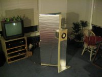
It kind of fires into a box first, but it's very crude. The opening from the driver enclosure into the triangular column is 3-4 inches square. I just took a knife and cut an opening and then enclosed it, based on what the driver baffled needed.
Do you think playing with that opening would help? I figure I could take the driver baffle off maybe two more times before completely destroying the foam in that area.
I also thought of cutting away the 6-inch wings above and below the driver. Sort of leaving it hanging out in front of the triangular part, but I need some input from more experienced people on what effects these things will have.
Is this the final design? Not even close, although it sounds promising as is. I am only sketching with a pencil right now. The final painting is a long way off. Right now, I need to bring back some of the clarity in the mid-range and highs. I also want to make the whole thing smaller.
Doug
My version for the fostex fe108.
Size is manageable and so is WAF
http://www.auricles.com/new_page_9.htm
Size is manageable and so is WAF
http://www.auricles.com/new_page_9.htm
Taperwood said:
The sound of the X-Baffle:
Overall, I think this is a design worth pursing further. I need to find a way to get the mid and high clarity back. Plenty of bass, though. If anyone has any specific experience in putting mid and upper range clarity back into a design, I would love to hear it. I want to try at least one more foam prototype before cutting some wood. I think plywood is required, due to the large surfaces. Any reasoned input?
Doug
Hmmm -that's one creative design. I like it! And once built from a decent ply or hardwood (or veneered MDF etc etc) I see no reason why your good lady could object, except in terms of the box's size, rather than its aesthetic appeal. It looks to me as if it will behave rather like a TQWT loading in certain respects. Try adding a top-panel to reduce the size of the vent as a quick and simple start. You could also try reducing the volume of the square chamber I believe you said the driver is mounted into fractionally.
Definately worth pursuing.
Best
Scott
kiang said:My version for the fostex fe108.
Size is manageable and so is WAF
http://www.auricles.com/new_page_9.htm
And another interesting one. Out of interest, any internal plans / layout, or would that be asking for the divulgance of secrets?
Cheers
Scott
Hi,
Interesting, fast and cheap way to build a prototype to get a first impression. I´m just a little worried if it is gonna give a good impression. In my opinion the foam will absorbe a lot of energy. In case of the horn, it wil absorbe instead of reflecting the energy at the rear of the speaker. This is why the speaker will produce low sound pressure in the low frequenties. And in case of the X-baffle the mid frquenties wil be absorbed by the baffle instead of reflected.
Another example of how importend the used material is. In case of a horn it is best to use multiplex instead of mdf, because mdf will absorde the energy, multiplex won´t. Horns build of mdf will give less bass and wil sound "dead". So if the difference between multiplex and mdf is that big, imagine the difference between foam and multiplex.
So I know you will have to start somewhere, but be carefull with your conclusions.
I really like the looks of the X-baffle, good luck with your project.
Alexander
All you need is a Fi X to match
Great thinking Doug,
Try this. allow the driver to fire into the large triangle by way of a duct that is circular (PVC pipe, carboard carpet tube, make something e.t.c.) or if it is 4 sided out of foam, make it so it flares into a larger size to the rear, maybe 4 or 5 times the area of the front sorta kinda like a square cylinder where the rear is about 4 or 5 times the area of the front and try it without the back wall of the large triangle,IOW
like a triangle.
Andrew
Ok, here's what I did tonight. I had to work today, so I had all day to think about everyone's input so far (thank's, by the way, I do appreciate it). My main concern right now is to restore the clarity in the midrange and highs. Get back the 'sizzle', so to speak. The easiest one was to try reducing the size of the vent at the top. 80 percent reduction cut the bass too much. 50 percent just didn't sound right. 25 percent reduced the bass enough to bring the speaker into better balance, low's, mid's, and high's, but it still didn't help the clarity issue.
I then considered changing the box behind the driver, but that would require too much surgery right now. I don't feel ready to do that yet.
So I cut off the top part of the 6-inch X-baffle, above the driver. That did it. The midrange and highs opened up beautfully. No question about it. I could almost live with this speaker as it is now except for the resonance from the foam. It's like the reverb they put in FM radio. You notice it, but the sound is still very nice.
Here's a photo of what I did tonight. I then will have a bunch of questions. I want to build another prototype. Something closer to a final design.
Doug
Attachments
Some questions:
1. In a TQWT design, what is the ideal pipe length for this driver? Or is that too vague a question? I'm seriously math challenged, so I need help on this. I can't do algebra at all. Right now, the pipe in the triangular column is 96 inches (243 cm) long. The driver is 16 inches (40 cm) from the small end of the pipe, which puts it 32 inches (81 cm) from the floor. I would like to reduce the overall size of the enclosure (wife's request). I could make the cabinet taller to compensate, if necessary.
2. Do I need some kind of compression chamber behind the driver? In looking at Fostex's back-loaded horn design, their chamber behind the driver is 1,566 cubic cm (17 cm x 18 x 6 minus blocks #29), and the opening into the horn is 35.7 square cm (17 cm x 2.1). This gives a chamber size to horn opening ratio of about 44:1. In my next prototype, I can build it so the driver fires directly into the pipe in the triangular column or I can put a compression chamber in first. I just need to know what is best for a TQWT design.
3. What do you think of a tapered design (see attached photo)? Do you think this would mess up the soundstage by reflecting sound downward? I much prefer this look to straight edges, but if it messes up the sound too much, I will stick with straight. One thing I did try with the existing prototype was to hang blankets over the large triangular panels. It totally killed the sound. So this proved to me that there is a lot of stuff happening off those surfaces.
Sorry for the rambling questions. Any input or help is greatly appreciated. I do seriously consider everything said so far. Some things I can't change right now, some things I will try at a later time, but everything so far has been a great help.
Doug
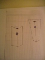
Some sketches for the next prototype:
I just noticed. The driver on the tapered sketch will be plumb. It won't fire downward.
1. In a TQWT design, what is the ideal pipe length for this driver? Or is that too vague a question? I'm seriously math challenged, so I need help on this. I can't do algebra at all. Right now, the pipe in the triangular column is 96 inches (243 cm) long. The driver is 16 inches (40 cm) from the small end of the pipe, which puts it 32 inches (81 cm) from the floor. I would like to reduce the overall size of the enclosure (wife's request). I could make the cabinet taller to compensate, if necessary.
2. Do I need some kind of compression chamber behind the driver? In looking at Fostex's back-loaded horn design, their chamber behind the driver is 1,566 cubic cm (17 cm x 18 x 6 minus blocks #29), and the opening into the horn is 35.7 square cm (17 cm x 2.1). This gives a chamber size to horn opening ratio of about 44:1. In my next prototype, I can build it so the driver fires directly into the pipe in the triangular column or I can put a compression chamber in first. I just need to know what is best for a TQWT design.
3. What do you think of a tapered design (see attached photo)? Do you think this would mess up the soundstage by reflecting sound downward? I much prefer this look to straight edges, but if it messes up the sound too much, I will stick with straight. One thing I did try with the existing prototype was to hang blankets over the large triangular panels. It totally killed the sound. So this proved to me that there is a lot of stuff happening off those surfaces.
Sorry for the rambling questions. Any input or help is greatly appreciated. I do seriously consider everything said so far. Some things I can't change right now, some things I will try at a later time, but everything so far has been a great help.
Doug
Some sketches for the next prototype:
I just noticed. The driver on the tapered sketch will be plumb. It won't fire downward.
Attachments
Taperwood said:1. In a TQWT design, what is the ideal pipe length for this driver? Or is that too vague a question? I'm seriously math challenged, so I need help on this. I can't do algebra at all. Right now, the pipe in the triangular column is 96 inches (243 cm) long. The driver is 16 inches (40 cm) from the small end of the pipe, which puts it 32 inches (81 cm) from the floor. I would like to reduce the overall size of the enclosure (wife's request). I could make the cabinet taller to compensate, if necessary.
A traditional TQW usually doesn't work all the well. A restricted terminus realy helps. Best to plug the driver into Martin's ML-TQWT model and play. Plugging it into his tables 1st will give you a good idea.
dave
Thanks, Dave. You actually answered questions #1 and #2 in your reply. I was hoping not to tangle myself in Martin's website, but if I must, I must. I can work with Fostex's ratios in the next enclosure re question #2. I might be able to build something tomorrow if I get enough time.
Doug
Doug
In all honesty, I'd leave the ML-TQWT idea with the FE108ESigma -this is a combination that just doesn't work. Of course, you can force it into anything you like, but this driver and cabinet type are pretty much incompatable. It's better in horns. I've been playing with the ML TQWT MathCad worksheet and this driver for a while, and nothing much works out -nothing I'd care to build at any rate.
As it happens, the worksheets aren't actually that difficult to use so long as you have a good basic understanding of how TLs in all their wonerful varieties work -remember, while the math looks frightening, Martin has done it all for you; all you have to do is insert the driver specs and play around with cabinet types and dimensions. OK, easier said than done, but don't be put off; intuitive it isn't, but it isn't that bad either.
Best
Scott
Ok, two strikes against using TQWT formulas, so scratch question #1. New question:
Is there a better length than 96 inches for the line length (I'm not even sure what to call it). In other words, how much distance should the backwave travel before exiting the cabinet?
I'm trying to estimate how tall, wide, or deep to make the next prototype. Right now, a 96-inch line sounds pretty good, but if I narrow the overall cabinet, should I make it taller to compensate? That's what I don't know right now. I have no experience, formulas, or rules of thumb to go by due to my inexperience building speakers.
Doug
There is no magic line-length that works unfortunately.
You want a Quarter Wave cabinet to be 1/4 of the wavelength of the frequency you're tuning it to. 60" is usually a good starting point. That gives a tuning frequency of about 40Hz with a driver like the Fostex FE167E. To drop that to 35Hz, you have to increase the length to around 84" etc etc etc.
However; next caveat: you can only go so low below the resonant frequncy of the driver. Tuning the system too far -trying to get say 35Hz out of the 108ESigma (resonant frequency about 77Hz I believe) will not be pretty. There's other factors as well. Fun, isn't it!
Best
Scott
Thanks, Scott.
At 96", I'm obviously way off the mark for a quarter wave design. But then, I'm not building that either. I went back to the Fostex back-loaded horn design and measured their horn length at about 77" (196 cm).
This is all very curious. I think I will try around 70-80" in the next prototype. I did want to make it smaller anyway. I'm dying to get two of these side by side to compare and ultimately build something out of wood, but work keeps interfering
I will report back when I have something put together.
Doug
Last week and over the weekend, I put together three more prototypes: #2, #3, and #4 (real original, huh?). I figured out how to front port them at the bottom to get some floor reinforcement.
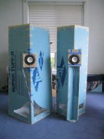
Right now, I am using Fostex's front-loaded horn specs for the compression chamber (1560 cm2) and vent size (62 sq. cm), and horn length (77 inches). Sizes are approximate, within 5 cm, due to foam not being real accurate. Driver height is 32 inches on all prototypes.
Box #2 (left) uses 18 inch sides but taper to 15" at the top. It's a folded horn with two internal baffles. The vent is at the top of the compression chamber. It lacks bass extension and loses some resolution. I do not think this design will work.
I learned on this one that lots of bracing tightens up the sound quite a bit, which is a positive sign for eventually building out of wood.
Box #3 (right). It uses 16 inch sides with the X-baffle being 3.75 inches. It too is a folded horn with two internal baffles. This one is not so overwhelmingly big. It has a Footprint of about 16 x 13 inches. Figuring the math and layout on this was a bear. It took me almost two days to build. It's built as accurately and tightly as possible.
The sound on #3 is really nice. Good bass into the 60 Hz range. There is something happening with the little wings in front. I've noticed this now on every prototype I have built. The speaker comes alive. I don't know what's going on here, but it's a totally different sound.
I also built a prototype #4. I will cover that in the next post. Here is a photo of #2 and #3.
Doug
Attachments
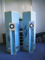
I concluded that prototype #3 is the best so far and one that I will focus on. Due to the difficulty in building this, I first wondered if I could get by with just one internal baffle by shortening the horn to the 60 inch range. This required placing the vent at the bottom of the compression chamber and using a single baffle to direct the backwave up and then down to the bottom of the cabinet. This experiment resulted in #4. Otherwise, #4 is identical to #3.
#3 kills #4 in A:B testing. I did a frequency sweep, and #4 dies out around 100 Hz, while #3 sounds clean and loud into the 80's and gives very usable bass in the low-60's. #3 has more resolution as well and just sounds louder and better. The sound of bass strings being plucked is very clear in #3, not so much in #4. There is no question; #3 is the one to go with. Unfortunately, it's going to be a bear to build out of wood.
I did some very critical listening this weekend on #3 and #4 with a variety of music. This design excels at small group acoustic music and vocals. Patsy Cline, "12 Greastest Hits," brought tears to my eyes. Mark Knofler, "The Ragpicker's Dream," lovely. Cowboy Junkies' "Trinity Session," better than ever. Classical sounds okay if a bit distant. Jazz is really nice. Cassandra Wilson sounded great. Rock is the weak spot, but it's listenable.
So #3 is the one I'm going with. I will do a box out of MDF first and then finally see how the foam prototype compares. I have a feeling it will do fine, as it sounds really nice as is.
I have more pics of the construction of #3 if anyone is interested. I plan to build the MDF enclosure over the next few weeks.
Prototype #4 is on the left, #3 is on the right.
Doug
Attachments

- Status
- This old topic is closed. If you want to reopen this topic, contact a moderator using the "Report Post" button.
- Home
- Loudspeakers
- Full Range
- My Fostex FE108E Sigma project..