Hi Don,
I believe these large bits are intended for stationary routers. A 38mm bit on a hand router, well... be careful. The biggest router I found would not allow this without base plate (aluminium) modifications, so I decided to stop at 25mm. And I´m always happy when this part is finished and prefer routing with my smaller, better Festool router.
Generally, I would think that a large chamfer is a nice alternative and may even be used as a design element, as Scott suggests.
Somewhere I´ve read that a rule of the thumb for roundover radius is 1/10th of the baffle width or more to be effective. But surely, the more the better applies here, and with the largest roundover possible you´ll end up with a sphere, or nearby. This will have it´s own effects on the drivers response.
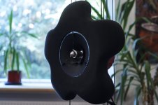
From another perspective, I find it interesting to care about transition from the driver´s cone to the baffle. In the flowers, I´ve tried to maintain the most even, undisturbed flare or path from the cone´s central area to the baffle edges, and I think that this is important. For that reason, I described the flowers, even with their funky look, as a form-follows-function design. The only design element without function is the polishing of the counterweight and the AE´s phase plug...
All the best
Mattes
I believe these large bits are intended for stationary routers. A 38mm bit on a hand router, well... be careful. The biggest router I found would not allow this without base plate (aluminium) modifications, so I decided to stop at 25mm. And I´m always happy when this part is finished and prefer routing with my smaller, better Festool router.
Generally, I would think that a large chamfer is a nice alternative and may even be used as a design element, as Scott suggests.
Somewhere I´ve read that a rule of the thumb for roundover radius is 1/10th of the baffle width or more to be effective. But surely, the more the better applies here, and with the largest roundover possible you´ll end up with a sphere, or nearby. This will have it´s own effects on the drivers response.
From another perspective, I find it interesting to care about transition from the driver´s cone to the baffle. In the flowers, I´ve tried to maintain the most even, undisturbed flare or path from the cone´s central area to the baffle edges, and I think that this is important. For that reason, I described the flowers, even with their funky look, as a form-follows-function design. The only design element without function is the polishing of the counterweight and the AE´s phase plug...
All the best
Mattes
Attachments
Interesting baffle shape here, more a wheel than a tyre ") https://www.diyaudio.com/forums/multi-way/123512-ultimate-baffle-gallery-319.html#post6426710
https://www.diyaudio.com/forums/multi-way/123512-ultimate-baffle-gallery-319.html#post6426710
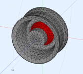
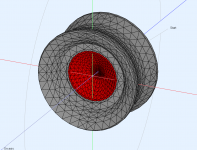
https://www.diyaudio.com/forums/multi-way/123512-ultimate-baffle-gallery-319.html#post6426710I simulated this "wheel" OB on Akabak 3 with 6 1/2" speaker and find torus like "tyre" seems better, specially in polar plot. Also this type OB drives Akabak to the limits. If I change meshing type (bifurcation vs. delaunay) or meshing size, even if mesh frequency is much higher than simulated range, I get very different results.
Some results. Wheel is: OD 260 mm, ID 172 mm, speaker 6 1/2.
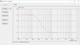
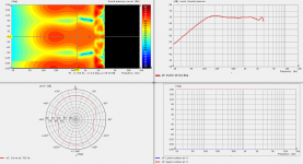
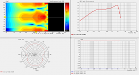
Polar plot is with 2 different speaker cone meshing versions. First Bifurcation, second Delaunay meshing. Simulations are one others copy in all other details. SPL curve is compensated with +15dB low shelf filter, to get usable mid response. Results are very different. I prefer Delaunay, but its level is obviously not correct, speaker has sensitivity 87 dB 2.83Vrms/1m. Simulation is also made on 2.83Vrms and for 1 m measurement distance.
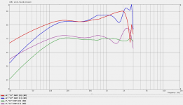
I added also on axis response comparison, C1 is Bifurcation front 1m, C2 rear 1 m, C3 is Delaunay front, C4 rear.
Polar plot is with 2 different speaker cone meshing versions. First Bifurcation, second Delaunay meshing. Simulations are one others copy in all other details. SPL curve is compensated with +15dB low shelf filter, to get usable mid response. Results are very different. I prefer Delaunay, but its level is obviously not correct, speaker has sensitivity 87 dB 2.83Vrms/1m. Simulation is also made on 2.83Vrms and for 1 m measurement distance.
I added also on axis response comparison, C1 is Bifurcation front 1m, C2 rear 1 m, C3 is Delaunay front, C4 rear.
Attachments
Last edited:
That's the plan for now Scott, 180mm centre hole for the driver, and outer diameter 540mm - not sure yet about driver mounting panel, surface treatment/finish, etc. Early days ...
Now playing with the curved baffle version (kerfed/grooved plywood) - simplified version of your 'kerdi-board V - the grooves at rear so curved in a parabola shape (to the back) and maybe also try grooves in the front surface to see if any reduction of baffle surface problems. Not as easy as I thought!
Hello again James, did you make anything?
FWIW here is a Falstad simulation of the torus baffle.
http://www.falstad.com/ripple/Rippl...+559+491+0 e+0+457+531+559+633+0 P+1+559+509
It has good blending with the cone slope so the front is more free of discontinuities than a spherical baffle. However any interruption of air space has a circumferential resonance, and the torus is no exception. You can see this in the form of the wavefront wrapping around the torus and re-radiating toward the front. What the torus does is it minimizes the possibility of waves re-radiating from discontinuities before they reach the rear.
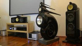
The circumferential resonance is what the long tail is for on the Nautilus speakers (image attached). On measurement microphones the concept is the same, rather than a flat back a long tail is preferred so that there aren't discontinuities at the back to re-radiate the wavefront forwards. Such features are visible in the impulse response.
Okay, to be fair I'm not exactly sure if this was the intent on the Nautilus, but I'd like to think so.
So if you want to improve upon the torus and the nautilus, I suggest giving the torus a teardrop shaped back with a long tail. This serendipitously provides a useful internal volume for an infinite baffle design. I suppose it can't be made into an open baffle without worsening the shape for diffraction. Hmmm...
http://www.falstad.com/ripple/Rippl...73+510 w+0+68+512+294+474 w+0+69+512+291+545
Being free of diffraction does not guarantee flat response (nor is it likely a meaningful way to identify the absence of diffraction), and I wonder what the resulting response would be. In theory adding tighter curve features on the front increases diffraction even if it appears to flatten out the response. So then there is the question of can we tolerate some response variation if it is free of diffraction, or do we go back on ourselves and start adding back diffraction when we don't like the response.
It should be noted that the smaller the tail, the more symmetry is required of the enclosure so that the wavefront converges on the tail because if it misses you get worse diffraction and might as well just use a shorter, stubbier tail.
The cross section looks like a heart, but I'm sure Cupid and Valentine are already taken as speaker names. Greek for heart is Kardia. I like that. Probably also taken.
http://www.falstad.com/ripple/Rippl...+559+491+0 e+0+457+531+559+633+0 P+1+559+509
It has good blending with the cone slope so the front is more free of discontinuities than a spherical baffle. However any interruption of air space has a circumferential resonance, and the torus is no exception. You can see this in the form of the wavefront wrapping around the torus and re-radiating toward the front. What the torus does is it minimizes the possibility of waves re-radiating from discontinuities before they reach the rear.
The circumferential resonance is what the long tail is for on the Nautilus speakers (image attached). On measurement microphones the concept is the same, rather than a flat back a long tail is preferred so that there aren't discontinuities at the back to re-radiate the wavefront forwards. Such features are visible in the impulse response.
Okay, to be fair I'm not exactly sure if this was the intent on the Nautilus, but I'd like to think so.
So if you want to improve upon the torus and the nautilus, I suggest giving the torus a teardrop shaped back with a long tail. This serendipitously provides a useful internal volume for an infinite baffle design. I suppose it can't be made into an open baffle without worsening the shape for diffraction. Hmmm...
http://www.falstad.com/ripple/Rippl...73+510 w+0+68+512+294+474 w+0+69+512+291+545
Being free of diffraction does not guarantee flat response (nor is it likely a meaningful way to identify the absence of diffraction), and I wonder what the resulting response would be. In theory adding tighter curve features on the front increases diffraction even if it appears to flatten out the response. So then there is the question of can we tolerate some response variation if it is free of diffraction, or do we go back on ourselves and start adding back diffraction when we don't like the response.
It should be noted that the smaller the tail, the more symmetry is required of the enclosure so that the wavefront converges on the tail because if it misses you get worse diffraction and might as well just use a shorter, stubbier tail.
The cross section looks like a heart, but I'm sure Cupid and Valentine are already taken as speaker names. Greek for heart is Kardia. I like that. Probably also taken.
Attachments
In my understanding waves in a continuous medium pass through each other, they do not bounce off of each other. This can be seen in the ripple tank. Plus, my examples have no rear wave, and the second is not an open baffle.
EDIT: What that means is that when two wavefronts overlap, they don't change direction just because they occupy the same space. It would be a different story if the air density of the wavefronts was significantly different as in a shockwave.
But that does make me realize that if it were an open baffle the back wave would effectively double the diffraction.
Last edited:
In fact it doesn't matter whether it actually does, or it only appears to, the result is the same.. only I didn't mention that the two will be of the opposite polarity.
Looking at this, notice that you have forward and rear radiation, and nulls. Each is reasonably clear and there are no other significant diffraction modes to cause response problems.
Looking at this, notice that you have forward and rear radiation, and nulls. Each is reasonably clear and there are no other significant diffraction modes to cause response problems.
Attachments
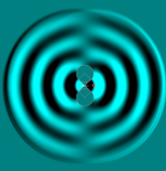
The simulation is visually misleading in this case. If you disable the rear radiator you will see that the forward wavefront wraps around the whole assembly and radiates forward again. This is true even if the rear source is radiating. So there is still a time delayed diffraction wavefront, even if it is hidden by the main wavefronts.
EDIT: This is why I also use the pulse source and not the sine source, so that all this is visible.
EDIT: This is why I also use the pulse source and not the sine source, so that all this is visible.
Here you can see the wrap around for each polarity if you look closely:
http://www.falstad.com/ripple/Rippl...6+0+2.944190050882948+2944.190050882948+-1+0
http://www.falstad.com/ripple/Rippl...6+0+2.944190050882948+2944.190050882948+-1+0
You are right, however this is what you expect a dipole to do, is it not? What is significant here as I see it is you have a fair spreading and stretching of that diffracted energy. It becomes less distinct because it's not concentrated in level, time or angle.. and reflected energy from the room walls is going to be more consistent due to the evenness at different axes.
An ideal dipole is just a pressure differential between two points in free air. It is the solid obstruction which is the torus that forces the wavefront to travel around a surface to get from point A to B, which in turn causes a time delay and redirection of the reverse wavefront back forward. So the diffraction is not a feature of a dipole, but a side effect of having a baffle.
The delay between the front and rear wavefronts could be seen as the effective spacing between the poles. Even a massless dipole will have comb filtering if the spacing between poles is larger than 1/2 wavelength of the max frequency.
Actually the effect of enlarging a baffle on an open baffle speaker would be to make it function LESS like a dipole. So now we are at Baffless. In which case how large does the torus really need to be, why not just follow the 1/10 roundover rule to determine torus size?
Last edited:
Diffraction is more than unwanted lobing. If sound didn't diffract around to the back then the null regions wouldn't form (this goes for non-acoustic dipoles as well).diffraction is not a feature of a dipole, but a side effect of having a baffle.
In a dipole, the poles themselves diffract to the degree that they are separated, but when they are separated they act like monopoles. If the other pole is 1 mile away, then it might as well be a monopole. Similarly, if the baffle is 20m in every direction, then it may as well be a monopole radiating in half space. If however the poles are 1mm apart, then for audio it may as well be an ideal dipole.
The null region forms whether or not there is diffraction just due to opposite fields summing at the balance point. Even with a 1mm separation of poles, there would still be a null region even though there is not enough distance to diffract at audio.
The null region forms whether or not there is diffraction just due to opposite fields summing at the balance point. Even with a 1mm separation of poles, there would still be a null region even though there is not enough distance to diffract at audio.
"summing at the balance point" implies that pressure combines and travels over the plane of the baffle, which occludes the source. Ipso facto diffraction.
This is further demonstrated by the shape of the null fanning out from the edge of the baffle, as well as the wavefronts radiating out from that point in all directions.
This is further demonstrated by the shape of the null fanning out from the edge of the baffle, as well as the wavefronts radiating out from that point in all directions.
Diffraction is defined as an interaction with an object, so a massless dipole would not have diffraction (by definition). So I was wrong to say that a massless dipole diffracts. It generates an interference pattern but does not diffract. Diffraction is actually evidence that your source is NOT behaving like a dipole, because it means there is something obstructing the poles, making them behave more like monopoles.
And yes, the torus shape helps it radiate more like a dipole.
However a dipole in open baffle does not reduce diffraction, it doubles it. Even though the pressure waves are opposite as they meet, their velocities are also opposite so they cannot cancel; they are moving in opposite directions. If you want to cancel out diffraction you need to change the polarity of the rear radiator. This way when the rear wave falls off the baffle, it inverts and then follows the reflection of the front wave. Since they both have the same direction but opposite pressure, they combine and cancel. You can see this in action by enabling the rear source with strength=1:
http://www.falstad.com/ripple/Rippl...48+2944.190050882948+1+0 w+0+505+349+505+668
What is it you look forward to in an open baffle arrangement, is it the rear radiation? Is it the side nulls?
(Side note) When someone comes up with the closed box idea of absorbing the rear wave (it's a coincidence that I'm talking about rear waves here) I say that you won't modify the system resonance Q factor with no rear wave. That part is wanted. The point is that something with a bad name isn't always unwanted.
(Side note) When someone comes up with the closed box idea of absorbing the rear wave (it's a coincidence that I'm talking about rear waves here) I say that you won't modify the system resonance Q factor with no rear wave. That part is wanted. The point is that something with a bad name isn't always unwanted.
- Home
- Loudspeakers
- Full Range
- Did Siegfried Linkwitz miss a trick?