I have long been looking at the Don Keeles CBT36 line arrays, but was intimidated by the insane amount of tweeters. Recently I happened to search for his work again when discussing speakers with a friend and noticed that now an other version exist, CBT24, that looks to be a somewhat easier build.
The kit has been discontinued by parts-express: Epique CBT24K Line Array Speaker Kit Pair
But inspired by Jim Griffin here I have started building my own (duplicating his build).
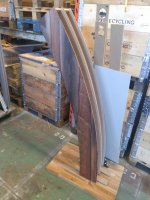
I have started cutting out parts for the enclosure (going to build the enclosures before blowing $1k on drivers ).
).
Image of the routing.
More images as the build progresses
I am a bit new to the world off full-ish range speakers that benefit from a subwoofer. If someone has any tips for a matching subwoofer build I would be happy for advices I will probably order parts from here: Audio Components
I have looked at these subwoofers: Seas E0026-08S W26FX001 and Dayton Audio RSS315HFA-8 12", should I have one or two subwoofer boxes?
The kit has been discontinued by parts-express: Epique CBT24K Line Array Speaker Kit Pair
But inspired by Jim Griffin here I have started building my own (duplicating his build).
I have started cutting out parts for the enclosure (going to build the enclosures before blowing $1k on drivers
).Image of the routing.
More images as the build progresses
I am a bit new to the world off full-ish range speakers that benefit from a subwoofer. If someone has any tips for a matching subwoofer build I would be happy for advices
I will probably order parts from here: Audio ComponentsI have looked at these subwoofers: Seas E0026-08S W26FX001 and Dayton Audio RSS315HFA-8 12", should I have one or two subwoofer boxes?
Last edited:
Great news to learn about your decision. You will be pleased with the results.
You are making good progress on the enclosure images.
Concerning the subwoofer one or two decision: I currently use two 12" diameter powered subwoofers with my arrays. The subs are spaced alongside each array. Your choice is more a factor of the size of your listening room and how even you wish to have bass coverage within the room. My listening room is large in both area and volume so essentially two subs serve to provide excellent sound.
When I first finished my arrays I used two 10" passive subs (CSS SX-10 drivers) with an old Yamaha R-9 stereo receiver to amplify those subs. This receiver provides plenty of power and it has EQ controls which permits bass boosting as you please. These subs are mounted in 1 cubic foot sealed boxes.
Later I replaced those two subs with an Eminence Lab12 driver in a 2 cubic foot sealed box. A Parts Express 250 watts plate amp with a 6 dB bass boost at 30 Hz is used in that configuration.
More recently I have added a SVS SB-1000 powered sub (yes a purchased speaker) to play alongside the Lab 12 unit.
The common trend with my sub adventures is that I like bass boosted sealed units vs. ported box designs but that choice is a personal decision so you may have different needs.
To drive my CBT arrays I originally used a Marantz NR1602 receiver which has 50 watts per channel output. It also provides a single subwoofer output which I used to drive my subs. The crossover frequency is set at 125 Hz inside the receiver. The NR1602 also has Audyssey MultiEQ for room correction.
More recently I have upgraded my electronics to a Denon AVR-X3600H HT receiver which yields 105 watts per channel to the arrays and has two subwoofer outputs. The Denon also has Audyssey MultiEQ XT32 room correction capability. Again the crossover is set at 125 Hz inside the receiver. While a 9.2 configuration HT receiver is a gross overkill for my current needs, the Denon has capacity for future improvements.
Last edited:
On my site: Vandermill-Audio.nl I have published free plans for 12" subs (using the Scan Speak 30W) that you could power with a Hypex FusionAmp FA501 or one of the Parts Express plate amps to make it active.
I've build two of those (small sealed with DSP boost) to go along my straight arrays.


The SVS subs are nice though!
I'd get at least two subs, even more is better for distributed bass. My arrays still play part of those frequencies alongside the subs.
I've build two of those (small sealed with DSP boost) to go along my straight arrays.
The SVS subs are nice though!
I'd get at least two subs, even more is better for distributed bass
. My arrays still play part of those frequencies alongside the subs.I have looked at these subwoofers: Seas E0026-08S W26FX001 and Dayton Audio RSS315HFA-8 12", should I have one or two subwoofer boxes?
The Seas 10" Excel is a great midbass, not nearly as great as a sub. The Seas L26RO4Y, however, is a beast of a sub. It's not the easiest to handle if you want a completely passive build but the performance is pretty much best in class. If you go active with DSP then that is of course a non-issue.
On my site: Vandermill-Audio.nl I have published free plans for 12" subs (using the Scan Speak 30W) that you could power with a Hypex FusionAmp FA501 or one of the Parts Express plate amps to make it active.
I've build two of those (small sealed with DSP boost) to go along my straight arrays.
...
The SVS subs are nice though!
I'd get at least two subs, even more is better for distributed bass
Nice looking subs! I have access to a great laser cutter so might duplicate your build! Amazing amount of screws thought:

Built like a tank
Looks to be a more complex build than the CBT24 array (in part count). I am thinking about using something like the Hypex FusionAmp FA251 for the subwoofers. Will probably get some DSP between source and CBT24/subs, so maybe better to get something like the UcD180HG (or parts-express plate amp, but I think the shipping to Sweden (and import taxes) would be horrible).
OllBoll: Thanks for tip about Seas L26RO4Y, I will take a look!
Glued and screwed, would you believe it? I had a large stash of those screws and figured it wouldn't hurt as there would be tension from those rods pulling the front baffle to the enclosure.
Take a good look at the dimensions, with laser cutting you could tighten the fit. I've done it all with a router and it was hard to determine what dimensions to put on the final drawings as I had the basic idea ready but finalised it on the go in the workshop.
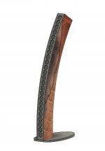
The logo cut drawing is linked on the site (lol). I'd be honored if you kept that detail.
The Hypex NCxxxMP-OEM modules are the same as in the FusionAmp, if you can get it separately.
Take a good look at the dimensions, with laser cutting you could tighten the fit. I've done it all with a router and it was hard to determine what dimensions to put on the final drawings as I had the basic idea ready but finalised it on the go in the workshop.
The logo cut drawing is linked on the site (lol). I'd be honored if you kept that detail
.The Hypex NCxxxMP-OEM modules are the same as in the FusionAmp, if you can get it separately.
Some more building done:
Assembling
Gluing
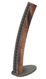
Thinking about finishing them with some veneer. Found some nice looking pieces that are almost big enough: veneer image
The piece have been exposed to moisture so they are a bit warped, I will see if I can get them flat.
Assembling
Gluing
Thinking about finishing them with some veneer. Found some nice looking pieces that are almost big enough: veneer image
The piece have been exposed to moisture so they are a bit warped, I will see if I can get them flat.
Jim,
I'm going to get started on the wire harness soon, two questions for you.
1. Did you put any dampening around the wires, and/or attach them to the inside of the cabinet?
2. How much stuffing did you put inside? About 1 kg for each enclosure?
Hjalmar
1. Damping around wires seems excessive. As the size of the obstruction corresponds to the frequency you'd have to go up pretty high in frequency to "see" the wire. And that high up the stuffing around the box will absorb it anyway.
On 2. with amount of stuffing the others will have to pitch in. Are we talking about the sub or the array here?
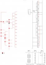
On Wiring of Arrays and Stuffing
I estimate more than 100 feet of 16 gauge wire were needed for the weighting network cable assemblies in my prototypes. I decided to construct three separate wiring cables for each speaker enclosure. The cable assemblies are for the bottom 12 drivers, the middle 6 drivers, and finally the top 6 drivers. These three sets of cables were intended to be tied together near the bottom of the cabinet close to the terminal plate location.
I used six colors of cable to help me discern each cable set as I went along. These color coded cables and the driver connection pins were assembled to scale outside the enclosure and then pulled through the cabinet into position. I stretched a line of painters tape along my work bench to allow me to mark at the driver placement dimensions (2.625”center-to-c enter between the drivers) for assembly of the wiring harnesses before insertion into the cabinet. I carefully labeled the various wires so that the destinations and polarities were clear as the wires were as placed into position. I used wire ties to tie the wires together as I went along this layout. I allowed extra length so that I could later attach the wires to the drivers outside of the cabinet and leave enough length to connect the wire together at the bottom of the cabinet.
As many three-way connections were needed for the weighting networks inside the cabinets, a common 3M Scotchlok connector was modified from a 1 to 2 way connection to be a 1 to 3 connection by hand drilling out the through wire stop.
With the cabinet standing vertically in my shop, I was able to use gravity to pull the wiring harnesses into place inside the cabinet with the wires emerging from the drivers holes.
I used Acousta Stuf sound damping material to fill the enclosed volume of the cabinets. The AcoustaStuf material comes matted together so I make an effort to pull the fibers apart. The goal is to fill the internal cavity of the cabinet with fluffy stuffing yet not compress the damping material inside the speaker. I did not measure the stuffing weight but it is likely within your figure. I use the stuffing to keep the wiring in place near the back of the cabinet.
Last edited:
Since I guess you also live in Sweden I can recommend nice stuffing that also comes in sheets (and doesn't itch like fiberglass!): Hifikits sheet wool. It performs really well too, even better than fiberglass.
1. Damping around wires seems excessive. As the size of the obstruction corresponds to the frequency you'd have to go up pretty high in frequency to "see" the wire. And that high up the stuffing around the box will absorb it anyway.
On 2. with amount of stuffing the others will have to pitch in. Are we talking about the sub or the array here?
1. Mostly thought about if there is any risk of rattling from the wires.
2. The line array, the sub will be a project after finishing the CBT24
Jim:
I think maybe I will install the wires before closing the enclosure. Lots of labeling and colors will be needed, quite complex wiring for a speaker
And I will probably use these kind of connector for everything: three way connector
Thanks for the note about the stuffing!
OllBoll:
Yeah, I will order most parts for the build from hifikit.se, I don't like fiberglass so either the sheet wool from hifikit or plain wool.
Concerning my use of the 3M Scotchlok connector: Normal this connector has one input wire and two outputs but with the stop removed it becomes a one input and three outputs connection. Thus you can make those one to three connections which are needed for my version of the weighting network. Essentially, you need to have this 4-way connection capability.
The connection block you linked appear to have the capability that I'm suggesting in some of the more complex models but it is more than a three way connection.
On assembly of the speaker: Yes, I do suggest that you wire and stuff the cabinet before you screw the drivers into the cabinet. I'm assuming that you have a closed back. Note that the speaker holes are small but you will need the ability to reach and guide the wires inside the enclosure. Small hands or reaching tools can be useful. Now a removable rear baffle would be nice but that adds more complexity. Make sure that you maintain the polarities of the connections as in the wiring diagram.
Instead of a 4-way I can use an additional 3-way, I made this (see attachment) before I got the presentation from you Jim that showed how Don Keele made it.
Yeah, removable rear baffle adds unnecessary complexity, I meant that I would assemble the wire harness and put it in the enclosure before gluing the baffles in place
Yeah, removable rear baffle adds unnecessary complexity, I meant that I would assemble the wire harness and put it in the enclosure before gluing the baffles in place
Attachments
Looks like the veneer will be fine. Anyone want to give input on how I should align it? ^^ I made two variants by pasting the photo over the model in GIMP.
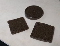
And wesayso, I think I will just take some ideas from your build and do a little bit different design. The frequency response from the Scan speak 4558T00 looks really nice, but I have been wanting to test making something out of epoxy granite, so I will probably use that for the enclosures. I did some tests with just stonemeal and epoxy (5 parts stone, 1 part epoxy). If I make the enclosure 15 mm thick, total weight should be about 30kg.
And wesayso, I think I will just take some ideas from your build and do a little bit different design. The frequency response from the Scan speak 4558T00 looks really nice, but I have been wanting to test making something out of epoxy granite, so I will probably use that for the enclosures. I did some tests with just stonemeal and epoxy (5 parts stone, 1 part epoxy). If I make the enclosure 15 mm thick, total weight should be about 30kg.
Attachments
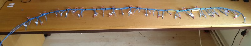
Very neat wiring harness! Great progress.
My connections to the drivers were likely longer than yours as I made sure that I had more than adequate length for all connections outside the cabinet. I wanted to have room to insert the wiring harness, place the harness in the back of the cabinet, fill with the damping material, and then have enough space to make the connections. If you glue the baffle into the cabinet after these operations, should allow you to have shorter wiring vs. my procedure.
One note on more careful reading of your comments in Posting #15: My Modified CBT24 weighting network is for the 4 ohms SBA65 drivers which has different wiring vs. Keele's design with his 16 ohms drivers used in the Dayton Audio CBT24 version. I haven't compared your diagram to my wiring schematic but be sure to test your harness before final installation in the cabinets.
Last edited:
- Home
- Loudspeakers
- Full Range
- Modified CBT24