Be aware that it is great to have individual control over each driver in an array. But it could be both a blessing and a curse. You'd have almost unlimited possibilities controlling each driver like that. That isn't a small feature to control. Do you know what you want each driver to do?
Up till now you've optimised your speakers by getting each individual component to do its part, after which you let them play together. However a line of drivers that actually have to work together is a whole new ball game.
By the way the MMS of both these drivers mentioned are quite close...
Up till now you've optimised your speakers by getting each individual component to do its part, after which you let them play together. However a line of drivers that actually have to work together is a whole new ball game.
By the way the MMS of both these drivers mentioned are quite close...
mark100,
I checked the Parts Express listing for the TC9FD units and you are correct on the listed weight of these drivers. It is 0.7 lbs each or 16.8 lbs for 24 drivers or 14 lbs it you use 20. Still more than double the SB65 drivers but more manageable than my first comparison.
But with the larger/heavier heavier driver I suspect that your enclosure volume will be larger than my cabinets so design your structure accordingly. The weight of the CBT cabinets I used balances well with an offset double thickness base so you likely will not have an issue if your array shadow and base length are similarly designed. You can also increase the base thickness/size or use a more dense material (metal anyone?) to help balance the array when standing. You may need to have different bases for a straight array version vs. an offset curved CBT implementation. If you have kids or large dogs, consider the balance issue so that safety is maintained.
Last edited:
Be aware that it is great to have individual control over each driver in an array. But it could be both a blessing and a curse. You'd have almost unlimited possibilities controlling each driver like that. That isn't a small feature to control. Do you know what you want each driver to do?
Up till now you've optimised your speakers by getting each individual component to do its part, after which you let them play together. However a line of drivers that actually have to work together is a whole new ball game.
By the way the MMS of both these drivers mentioned are quite close...
Hi Wesayso,
I haven't contemplated any individual control of the drivers, other than the normal amplitude shading for the curved array.
And the delay and amplitude shading for the straight line,
if i want to play with beam steering or mimicking CBT.
That all seems pretty straightforward so far...
I'm not envisioning any frequency response adjustments at the driver level.... that's one of the beauties of a line i think
Is my understanding correct, that mag and phase adjustments for line-arrays should be done globally ?
mark100,
I checked the Parts Express listing for the TC9FD units and you are correct on the listed weight of these drivers. It is 0.7 lbs each or 16.8 lbs for 24 drivers or 14 lbs it you use 20. Still more than double the SB65 drivers but more manageable than my first comparison.
But with the larger/heavier heavier driver I suspect that your enclosure volume will be larger than my cabinets so design your structure accordingly. The weight of the CBT cabinets I used balances well with an offset double thickness base so you likely will not have an issue if your array shadow and base length are similarly designed. You can also increase the base thickness/size or use a more dense material (metal anyone?) to help balance the array when standing. You may need to have different bases for a straight array version vs. an offset curved CBT implementation. If you have kids or large dogs, consider the balance issue so that safety is maintained.
Thanks again Jim,
Right now I'm trying mimic two box designs...yours and John Murphy's corner box.
My first sketches of those are calling for a baffle 4.5" wide minimum.
On the curved array, the baffle will bolt straight to side edges, so the speaker will be baffle width.
On the corner box, the baffle will bolt to vertical cleats running up the entire back of the angled pieces that the baffle joins. The box will be about the same size as Murphy's.
And yes, I'm now turning attention to safe strong bases.
One like yours for the curved. And two for the straight...one for freestanding, and one for in the corner that gets the straight box up over protruding base and shoe molding, and fully nested into the corner (and makes sure it can't fall outward.)
The hardest thing so far has been figuring out a wiring harness that stays with the driver baffle, and gives external access with both boxes.
I think I've come up with a reasonable solution, but I've already had to ditch the phoenix connector idea...it got complicated and expensive.
Yes, but you could do so much more!
Have you done any tuning of individual drivers, or blocks of drivers?
Fingers crossed, ready to learn
bendability of BB
A quick experiment:
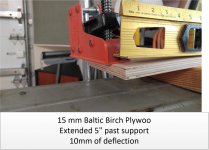
I don't have a curved form so I measured deflection. I clamped down one end of 15 mm scrap of baltic birch on top of a 2x4 and pulled the other end down with another clamp.
I could have gone further, the wood wasn't showing signs of stress but this is as far as I would need to go in my wildest imaginings and probably twice as far as needed for a 2.5" driver. My only concern was how much force was required; I could not have bent it that far by hand.

A quick experiment:
I don't have a curved form so I measured deflection. I clamped down one end of 15 mm scrap of baltic birch on top of a 2x4 and pulled the other end down with another clamp.
I could have gone further, the wood wasn't showing signs of stress but this is as far as I would need to go in my wildest imaginings and probably twice as far as needed for a 2.5" driver. My only concern was how much force was required; I could not have bent it that far by hand.
Attachments
Have you done any tuning of individual drivers, or blocks of drivers?
Fingers crossed, ready to learn
No sir! I have had my hands full with the number of things I actually can control. Many choices available within DSP alone, lots more if you add any number of other variables like ambient channels etc. All of those are individually controllable, so it has limitless room to play with. I experience that as both good and bad
.A quick experiment:
I don't have a curved form so I measured deflection. I clamped down one end of 15 mm scrap of baltic birch on top of a 2x4 and pulled the other end down with another clamp.
I could have gone further, the wood wasn't showing signs of stress but this is as far as I would need to go in my wildest imaginings and probably twice as far as needed for a 2.5" driver. My only concern was how much force was required; I could not have bent it that far by hand.

Oh my, I buy BB because it won't bed Lol
I bought a sheet of 1/4" furniture grade birch face plywood today.
I'm going to split it lengthwise, and glue it up to make a 1/2" laminate.
I think this will work well for the driver baffles, and CBT's rear panels.
And I found 12mm BB in 4x8 sheets for the CBT's sides and straight-line boxes.
Yay! 5'x5' is always available, but 4'x8' can be tough to find...
As long as you have enough foam behind each driver to not bend the frames to conform with the bent baffle (and still have a good air seal), you won't have dragging voice coils...I bought a sheet of 1/4" furniture grade birch face plywood today.
I'm going to split it lengthwise, and glue it up to make a 1/2" laminate.
I think this will work well for the driver baffles, and CBT's rear panels.
As long as you have enough foam behind each driver to not bend the frames to conform with the bent baffle (and still have a good air seal), you won't have dragging voice coils...
Hi Art, thank you for that heads up!
If I ran the numbers right, the arc that is formed over the span of one 3.3125" diameter driver, has a height of only 0.01".
Do you think I would need any foam/gasket for that small of an arc?
(I'm wading in new territory
For what it's worth, I did a short expose' on my line array variant speakers over at AVS forum.
Radical Speaker Design - AVS Forum | Home Theater Discussions And Reviews
These deviate a little from the fractal array concept I posted about on this forum:
Fractal Array Straight CBT with Passive XOs and no EQ
The speakers go flat on a wall, rather than in a corner.
The reason I bring this up is that with the multi-way concept (mine is a 4-way) you can change the beamwidth by changing the frequency range of each "way". So if you had an active setup, you could power each speaker with 4 amps. If you want the beamwidth narrow, then keep the crossovers high. If you want the beamwidth wide, move the crossovers lower. Since mine uses an actually tweeter, there's limits to how much change you could make, but the concept could be adjusted to make sure the range of crossover frequencies could be wider. That way you get beamwidth control with way fewer amps. It wouldn't be possible to angle the beam though.
Without a foam gasket, any deviation from flat will warp the cone, though .01" probably wouldn't hurt anything. That said, why bother with that small of an arc if you are planning to use individual speaker processing?Hi Art, thank you for that heads up!
If I ran the numbers right, the arc that is formed over the span of one 3.3125" diameter driver, has a height of only 0.01".
Do you think I would need any foam/gasket for that small of an arc?
(I'm wading in new territory
And why bother with "beam steering" unless you are forced to mount the speaker overhead on a wall (as pointed out by wonderfulaudio post #28) ?
Using a yolk (like a lighting fixture) or a balanced tilter would save a lot of engineering for instances where you need a down or up angle.
Art
Last edited:
For what it's worth, I did a short expose' on my line array variant speakers over at AVS forum.
Radical Speaker Design - AVS Forum | Home Theater Discussions And Reviews
These deviate a little from the fractal array concept I posted about on this forum:
Fractal Array Straight CBT with Passive XOs and no EQ
The speakers go flat on a wall, rather than in a corner.
The reason I bring this up is that with the multi-way concept (mine is a 4-way) you can change the beamwidth by changing the frequency range of each "way". So if you had an active setup, you could power each speaker with 4 amps. If you want the beamwidth narrow, then keep the crossovers high. If you want the beamwidth wide, move the crossovers lower. Since mine uses an actually tweeter, there's limits to how much change you could make, but the concept could be adjusted to make sure the range of crossover frequencies could be wider. That way you get beamwidth control with way fewer amps. It wouldn't be possible to angle the beam though.
Yes, thank you. A friend had already PM'ed me your design to look at.
Very interesting, nice work.
If I can master vertical beamwidth, maybe I can move on to adding in horiz too

Without a foam gasket, any deviation from flat will warp the cone, though .01" probably wouldn't hurt anything. That said, why bother with that small of an arc if you are planning to use individual speaker processing?
And why bother with "beam steering" unless you are forced to mount the speaker overhead on a wall (as pointed out by wonderfulaudio post #28) ?
Using a yolk (like a lighting fixture) or a balanced tilter would save a lot of engineering for instances where you need a down or up angle.
Art
Art, the small arc per driver isn't intuitive I think....
the CBT's 36 degree arc leans back a full 2 feet at the top with a 7ft tall array.
But the arc height spanned by each of the small drivers is next to nothing.
The biggest reason for this project is to play with what's in this paper..
https://keele-omholt-technologies.com/papers/Keele-2005-10-AES-Preprint-CBT-Paper-5.pdf
Time to learn something new...and hopefully hear something new too
PS....You know the Jasper circle cutting router jigs ...?
Today I'm making a DIY jig for cutting circles up to 11ft radius ....
Each new project has as much to learn with tooling as anything, huh ?
Last edited:
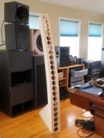
Ok, a dual CBT / straight-line 'Murphy corner' project is underway.
CBT boxes are about ready to assemble; the straight-lines aren't far behind.
Both use the same removable driver baffles with 24 TC9's.
So I can only run one setup at a time (in stereo that is)
Finally settled in on wiring 6 groups of 4 drivers.
Hopefully, that should accommodate shading for the CBT, and delay/shading for straight-line steering experiments.
It will also allow all drivers to be run off 1 channel for 5+ohm load in "corner mode"
Stoked! ....Other than dreading mounting all the damn drivers LoL
Attachments
The shading--approximation of a Legendre roll-off--in Keele's CBT24 and my Modified CBT24 designs are applied in a group of 12 (the lowest drivers to the floor), a group of 6 (upper middle) and finally a group of 6 for the top drivers. The weights are 0 dB for the lowest 12 (achieved via wiring of the drivers in series-parallel) then 3 dB down for the next 6 drivers (achieved by connections and fewer drivers) and finally 9-10 dB down for the final 6 (achieved by connections and a two resistor divider network). Of course with beam steering you can have finer graduations for the approximation depending on the number of channels you allocate which is a good thing.
Last edited:
Great progress. I guess your super sized circle jig worked
Thanks! Yep, 10' 8.5" radius.
- Status
- This old topic is closed. If you want to reopen this topic, contact a moderator using the "Report Post" button.
- Home
- Loudspeakers
- Full Range
- Line array steering ?