Lesson learned : wall impedance is important, and foam core is not usable for resonant designs.
Small undetected air leaks will also adversely affect performance.
Foam core is not really suitable for any loudspeaker enclosure panel
") .
.Seeing the tape applied to the driver, I can definitively say there must be air leaks .. and those will throw off the impedance measurements.
I tried before, there is no way to tape a driver in place, not good for edges either... the only way was to glue paper edges.
Actually, foam core is quite good with the mini-karlsonator that X came up with... sounds better than my 12mm plywood one!
It's also good for prototyping some special enclosures that would be expensive and time consuming if built in plywood.
I measure, and then if it looks suspicious, I go looking for leaks. The tape is applied in stages to see if the readings change. In this case it didn't help at all.
The foam core is first hot glued, then an application of caulking is applied to seal the seams from the inside and outside. I still think the problem is flex in the foam core. Test coming up.
The foam core is first hot glued, then an application of caulking is applied to seal the seams from the inside and outside. I still think the problem is flex in the foam core. Test coming up.
Small undetected air leaks will also adversely affect performance.
Foam core is not really suitable for any loudspeaker enclosure panel
Foamcore "might" be useful for a horn.
On the BP8, I could lightly touch my finger to a side panel and change the impedance profile.
At some frequencies it worked, and it was amazing. Bass Reflex 4.5L Cylinder
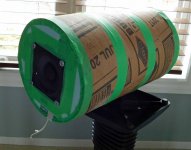
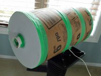
The same design as before, only implemented in a cylinder with stiffer walls.
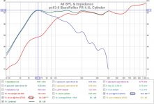
The bass extension response matches what was predicted in HornResp. I get a flat combined response from 600 Hz down to 60 Hz. No more saggy bass when using stiffer walls. The port and driver are on opposite sides so they were measured seperately and combined (green curve) So I think it is behaving properly from the FR perspective. However .....
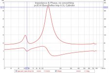
I still have to address the impedance curve issue. In my other larger driver designs (8", 12") I can get symmetric peaks. With this smallish driver I always get asymmetric peaks. Although the peaks are more defined now, there is a 2:1 difference in the amplitudes that I cannot seem to correct. I have tried taping, sculpting open the driver rear path, filling, and port length adjustment. Nothing will raise that first "mole hill into a mountain". Perplexed
The same design as before, only implemented in a cylinder with stiffer walls.
The bass extension response matches what was predicted in HornResp. I get a flat combined response from 600 Hz down to 60 Hz. No more saggy bass when using stiffer walls. The port and driver are on opposite sides so they were measured seperately and combined (green curve) So I think it is behaving properly from the FR perspective. However .....
I still have to address the impedance curve issue. In my other larger driver designs (8", 12") I can get symmetric peaks. With this smallish driver I always get asymmetric peaks. Although the peaks are more defined now, there is a 2:1 difference in the amplitudes that I cannot seem to correct. I have tried taping, sculpting open the driver rear path, filling, and port length adjustment. Nothing will raise that first "mole hill into a mountain". Perplexed
Attachments
Last edited:
I'm not certain why you worry about the impedance peak symmetry. Under normal circumstances, this will only happen when Fb=Fs, which does not appear to be the case here, where Fs=82Hz (as per spec sheet) and Fb~63Hz. Change the tuning to Fs and you'll see the peaks even out, not that this is necessarily a goal here.
I might be expecting too much from this. The Impedance peaks don't need to be exactly equal but more similar than they are now. Even though the box tuning is correct, it appears that the first peak is over damped. It might be from such a small port diameter or something else.
I would expect the first bump amplitude to be a "little" lower amplitude than the second bump amplitude because the box is tuned lower than driver Fs. In my case the first bump is a lot lower.
I would expect the first bump amplitude to be a "little" lower amplitude than the second bump amplitude because the box is tuned lower than driver Fs. In my case the first bump is a lot lower.
Last edited:
Did you measure the T/S parameters on your driver? I'd venture to say its Fs is slightly higher than published, which would account for the lower impedance peak's lesser amplitude as the actual Fs is further from Fb vs simulation. Suspension stiffness also often differs, causing both Fs and Qm/Qt variations which is reflected in the maximum impedance.
Thanks @IC81 for the suggestions. No, I didn't measure this driver T/S and that would be interesting to see how close they are to the spec sheet.
I did suspect the driver parameters at one time but when I varied them in hornresp I could not replicate the impedance behaviour I'm seeing. Hornresp has been very good at predicting the impedance profiles on my other designs (different threads) so I have a bias to believe it.
More recently I decided to test my "too small (3cm) port" idea and tried another solution using a larger port diameter (5cm) and longer pipe length. The peaks are in the same location, only the lower peak increased from 15ohm to 18ohm. A small amount of poly stuffing in the port will erase the first impedance bump.
Last edited:
Actually, foam core is quite good with the mini-karlsonator that X came up with... sounds better than my 12mm plywood one!
I would have expected an identical enclosure made of presumably more rigid and more dense plywood to perform better than one constructed of foamcore. Perhaps the foamcore is serving a double purpose in the mini-karlsonator design by also acting as an absorbent lining, outweighing its physical shortcomings in other areas?
It's also good for prototyping some special enclosures that would be expensive and time consuming if built in plywood.
Agreed, but just don't expect simulation predictions and actual measurements to match all that well
.Foamcore "might" be useful for a horn.
Concrete would be better
.I could lightly touch my finger to a side panel and change the impedance profile.
Sounds a bit like the dent tuning of microwave radio system feeder waveguides to improve return loss / VSWR - a technique I was involved in using myself, many years ago...
Attachments
Tractrix
I decided to try another horn. If cardboard worked, maybe foamboard would work as well. Ideally I'd like a low distortion midrange 800Hz-4000Hz range with some gain (>6db over bare driver).
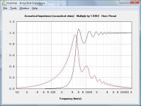
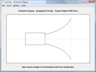
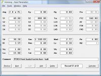
This time it's a rectangular tractrix. HornResp snapshots below.
I decided to try another horn. If cardboard worked, maybe foamboard would work as well. Ideally I'd like a low distortion midrange 800Hz-4000Hz range with some gain (>6db over bare driver).
This time it's a rectangular tractrix. HornResp snapshots below.
Attachments
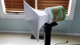
Tractrix - built
It's a little tricky to bend foamboard. The panels have been scored on one side at regular 1cm interval then bent. The panels were hot glued together, then the interior surfaces were "painted" with hot wax to create a smooth surface.
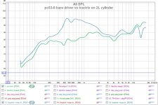
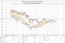
It still has that "saddle" shape in the FR like the other horns. The horn gain in the 400-1.2Khz region is significant compared to the stock driver (graph#1). The distortion is also reasonable at -50db at >400Hz (graph#2).
I wish I could increase the horn gain in 2Khz-4Khz region. Suggestions, anyone ???
It's a little tricky to bend foamboard. The panels have been scored on one side at regular 1cm interval then bent. The panels were hot glued together, then the interior surfaces were "painted" with hot wax to create a smooth surface.
It still has that "saddle" shape in the FR like the other horns. The horn gain in the 400-1.2Khz region is significant compared to the stock driver (graph#1). The distortion is also reasonable at -50db at >400Hz (graph#2).
I wish I could increase the horn gain in 2Khz-4Khz region. Suggestions, anyone ???
Attachments
I wish I could increase the horn gain in 2Khz-4Khz region. Suggestions, anyone ???
You could add a phase plug to get some gain at higher frequencies.
Phase Plugs
Even simpler than 'simple' type would probably be fine, e.g just a wedge.
Some commercial horns have a phase plug that are approximately the shape of an axe head:
China Speaker Phase Plug 8 Inch Cabinet (084C) - China PRO Audio, Phase Plug
Alternatively: rebuild the horn, and make the throat smaller and asymmetric, such as a 6x3cm rectangle.
You could add a phase plug to get some gain at higher frequencies.
Phase Plugs
Even simpler than 'simple' type would probably be fine, e.g just a wedge.
Some commercial horns have a phase plug that are approximately the shape of an axe head:
I did try to reduce the throat area to 20cm^2 to increase compression ratio. It causes a resonance because a chamber is created with the cone.
I like the driver dust cap shapd phase plug idea. That would eliminate the chamber and increase compression. Easy enough to try. Thanks.
I did try to reduce the throat area to 20cm^2 to increase compression ratio. It causes a resonance because a chamber is created with the cone.
What does that mean - what measurable effect did it have?
See post 4 here, the purple and black lines on the FR plot:
Tweeter for coaxial mounting in midrange horn
With a 4" driver on a 2" throat, I could get it flat up to 4kHz, with a deep notch above.
Adding a few bits of fluff (weather sealing tape) to the chamber was enough to fill in this deep notch, so that (with eq to boost the HF), I could get it flat to 7kHz.
It didn't need rocket surgery - filling in a bit of the chamber and breaking up the symmetry was enough.
What does that mean - what measurable effect did it have?
Same effect as a previous horn at Dayton PC83-8 (3") test results It causes a resonance and creates nulls.
See post 4 here, the purple and black lines on the FR plot:
Tweeter for coaxial mounting in midrange horn
With a 4" driver on a 2" throat, I could get it flat up to 4kHz, with a deep notch above.
Adding a few bits of fluff (weather sealing tape) to the chamber was enough to fill in this deep notch, so that (with eq to boost the HF), I could get it flat to 7kHz.
It didn't need rocket surgery - filling in a bit of the chamber and breaking up the symmetry was enough.
Your example is a little different as you are using a JBL 2445 compression driver meant to drive a horn. This thread is using a cheapo PC83 full range driver adapted to a horn to see what I can get and understand horns.
After trying several phase plug designs I could not extend the horn gain.
Only the green line in my link was the JBL.Your example is a little different as you are using a JBL 2445 compression driver meant to drive a horn. This thread is using a cheapo PC83 full range driver adapted to a horn to see what I can get and understand horns.
After trying several phase plug designs I could not extend the horn gain.
The black line is a 4" cone driver tested with the same settings & position. I was surprised that it needed less eq thru the mids, and was close to being as efficient as the (14kg!) JBL driver.
The purple is the 4" with a high pass added. After adding the bits of fluff, the notch was largely gone, so (with ~5dB of HF boost) I could push the high pass point ~3kHz higher.
This 4" was the best of quite a few I tried, about 8 other 2-4" drivers ranged from almost as good to fairly meh.
The "tuning" appears to have been performed with a heavy foot.
The image shows standard elliptical waveguide - it looks a bit squashed by design
.The actual tuning was performed using a "G" clamp. The tricky part is determining where to position the clamp, and by how much to permanently "dent" the waveguide by tightening the clamp (the clamp is then removed). Return loss / VSWR is closely monitored while the localised dent is applied. The technique is more an art than a science, but very effective when done correctly
.- Home
- Loudspeakers
- Full Range
- Dayton PC83-8 (3") test results