Le Cléac'h Petal Horn
I was inspired by another thread Paper Horn constuction on making a horn from paper. I also discovered that HornResp Paper Horn constuction can generate coordinates for a pedal horn from a design.
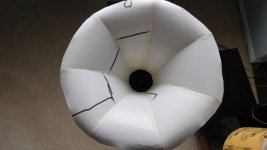
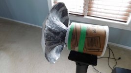
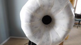
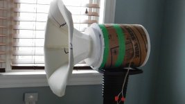
This one is made from recycled cardstock and hot glued foamboard flange, but I could also make this from sheet plastic or sheet metal 🙂.
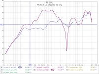
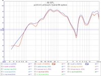
The horn gain (red curve) is in the 150Hz-1.5Khz range but unfortunately I also get a nasty null at 3.14Khz. The blue curve is for just a 3L cylinder without a horn, for comparison.
I was inspired by another thread Paper Horn constuction on making a horn from paper. I also discovered that HornResp Paper Horn constuction can generate coordinates for a pedal horn from a design.
This one is made from recycled cardstock and hot glued foamboard flange, but I could also make this from sheet plastic or sheet metal 🙂.
The horn gain (red curve) is in the 150Hz-1.5Khz range but unfortunately I also get a nasty null at 3.14Khz. The blue curve is for just a 3L cylinder without a horn, for comparison.
Attachments

Last edited:
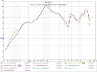
Le Cléac'h Petal Horn - 11 petals + rollover
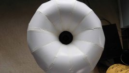
A more elaborate petal horn with the horn rollover. The performance is better, there is still significant horn gain plus some notches but not as bad as the 7-petal design. Not sure if it was more petals or the round over that helped
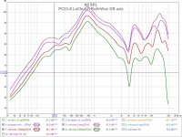
The first graph has no horn, 7 petal horn, and 11 petal horn. The second graph has by EQ attempt compared to the no horn setup.
A more elaborate petal horn with the horn rollover. The performance is better, there is still significant horn gain plus some notches but not as bad as the 7-petal design. Not sure if it was more petals or the round over that helped
The first graph has no horn, 7 petal horn, and 11 petal horn. The second graph has by EQ attempt compared to the no horn setup.
Attachments


The notch appears under all angles but a tad shifted in frequency. And there's a dip at the double and triple frequency too but both at different frequencies. That's a sign your paper-horn resonates. Try to stiffen it up with wallpaper-glue and newspaper parts, you can also use wood glue mixed with a bit water.
Thanks @ICG, sharp eye!, that makes sense. I'll try a few experiments to test that idea.
I was thinking of adding quick outer hot glue "ribs" to stiffen the wall structure. I should see the resonance points shift if its a wall resonance.
I was thinking of adding quick outer hot glue "ribs" to stiffen the wall structure. I should see the resonance points shift if its a wall resonance.
Not sure if it was more petals or the round over that helped
Are these all on-axis recordings?
It could be none of the above - maybe just be a wee difference in mic placement. I think most axisymmetric horns give a notch when you measure exactly on axis, but not elsewhere. Small differences in placement matter.
When I experimented, if I moved the mic a little off axis, the notch got smaller. If I intentionally introduced some asymmetry in the throat, the notch got smaller.
...so try measuring 30 degrees off, and see if it goes away completely.
This thread is some of the messing about I did:
Fostex FF105WK in conical horn
post 11 shows xrk971's quick but pretty nice horn*, post 14 is about the notch.
A less DIY but totally workable option is just to buy an off the shelf 2" horn; some wideband can work well on a 2" throat (even if the driver is bigger than 2"). Seller zxpc on ebay has some cheap-but-decent horns that might do the job, if you don't have anything handy locally.
The notch appears under all angles
What does "all angles" mean here?
*You can model these in hornresp. At one point, I made an 80cm wide, but otherwise similar horn from ply, also with a slot (about 4x10cm, from memory) as the throat shape. It measured better than the axisymmetric horns ...which is a shame, cos I think the axisymmetric ones look nicer. Also ,some building techniques require axisymmetric shapes.
What does "all angles" mean here?
Should I have said 'viewpoints' instead? Yes. Sorry, I'm not a native speaker and while a lot ppl tell me my English would be good, I still often struggle with expressing what I really mean. The horns are made the same way and looking at each plot they show the same behaviour but with a bit shifted frequencies. They are made the same way but with a bit different stiffness and variing sector sizes and the sector sizes are the exact reason why the resonances shift. That means if the resonance that shifts with the sector size it's tied to the way it's constructed. Or in other words, the construction of the horn is flawed and the sectors aren't stiff enough, which in turn means strengthen these parts will very likely change these resonances. Well, that was to be expected from the material used, isn't it? To design such a horn means to use the advantages and try to eliminate the unwanted/disadvantageous characteristics. Sometimes it's okay to ignore certain flaws if you know where they come from and concentrate on more important properties as long as you can return to that point to improve it or cancel it out by other means. In this case it's obvious the rigidity of the horn has to be improved to advance to the next step. To me, it was obious but please excuse my inability to express it short, precise and non-ambiguous. I'm working on it..
Should I have said 'viewpoints' instead? Yes. Sorry, I'm not a native speaker and while a lot ppl tell me my English would be good, I still often struggle with expressing what I really mean.
Your communication is more clear than many people who are native English speakers 🙂 This is just an example of the language being ambiguous and full of inconsistencies.
In this context I had 'angle' confused with measurement angle (microphone position).
Back OT:
I think silverprout's technique in the linked thread seems like a great way to prototype: using wax to thicken / stiffen the horn. Wax would be fast, not smelly, reasonably cheap. Also: it'd be good (non stick) for casting permanent horns from, once you got a 'perfect' shape.
Maybe it'd be useful to tape the horn together with plasterer's tape (which is a fibreglass mesh), and then apply the wax - because it would flow through the pores in the tape, it wouldn't leave any dry / weak spots on the paper.
'edible solid paraffin' probably means carnauba wax.
If buying wax by the kilo, art / casting supply stores sell (non edible) wax that also have a high melting point. They are a bit cheaper and might be easier to use than carnauba (less brittle).
Are these all on-axis recordings?
It could be none of the above - maybe just be a wee difference in mic placement. I think most axisymmetric horns give a notch when you measure exactly on axis, but not elsewhere. Small differences in placement matter.
They are on axis measurements. I have tried varying the distance and even measured vertical and horizontal and got the same basic result.
This thread is some of the messing about I did:
Fostex FF105WK in conical horn
post 11 shows xrk971's quick but pretty nice horn*, post 14 is about the notch.
Thanks for the link, always interested in different approaches. The "paper" horn looked like a way to generate a symmetric horn design. I understand that cardstock is not ideal but so far it allowed me to craft something from flat stock. The walls could be stiffened by material build up (wax, mache, foam insulation, etc) which I will try. I think there are also issues with the driver chamber size and throat adapter. At this point I'm still learning and still having some fun with a $10 driver.
A less DIY but totally workable option is just to buy an off the shelf 2" horn; some wideband can work well on a 2" throat (even if the driver is bigger than 2"). Seller zxpc on ebay has some cheap-but-decent horns that might do the job, if you don't have anything handy locally.
True, but I wouldn't learn as much, or enjoy it as much.
I think silverprout's technique in the linked thread seems like a great way to prototype: using wax to thicken / stiffen the horn. Wax would be fast, not smelly, reasonably cheap. Also: it'd be good (non stick) for casting permanent horns from, once you got a 'perfect' shape.
Maybe it'd be useful to tape the horn together with plasterer's tape (which is a fibreglass mesh), and then apply the wax - because it would flow through the pores in the tape, it wouldn't leave any dry / weak spots on the paper.
'edible solid paraffin' probably means carnauba wax.
If buying wax by the kilo, art / casting supply stores sell (non edible) wax that also have a high melting point. They are a bit cheaper and might be easier to use than carnauba (less brittle).
That's what caught my attention with @Silverprout's post. The paper trick is fast, especially when hornresp is used to sim the design then its also creates the petals as well. Applying the wax evenly could get tricky. It might just end up as "blobs" all over it unless it was gently heat gunned to get it flowing. Might give it a try. I'm sure I can find some budget wax at the dollar store 🙂
Applying the wax evenly could get tricky.
silverprout just painted it on with a brush, and it looks OK. Rewarming works, too: see the short video below.
I think you'd also rewarm if you wanted to add a 2nd layer once the first had cooled - you'd soften the base layer to make the next layer bond properly.
I'm sure I can find some budget wax at the dollar store 🙂
Brown Microcrystaline Wax - $/kg
This is pretty cheap, and looks perfect for the job.
The higher melting point (about 30°C above normal candle wax) means it won't deform from being too near your amplifier, or simply on a hot day - although I may define 'hot' differently to you, because Australia 😱
I just tried Carnauba (car wax) and paraffin (candle wax). Car wax has water which warps the cardstock and paraffin is very hard to control and always has that residual waxy feel. I suspect both will "creep" with time and temperature. So I'll look for a different material.
It would be possible to hot pot melt the wax and apply it with a brush as Silverprout has done, except I now don't like wax as a material.
It would be possible to hot pot melt the wax and apply it with a brush as Silverprout has done, except I now don't like wax as a material.
Last edited:
I just tried Carnauba (car wax) [...] I'll look for a different material.
I'm guessing car wax is a blend. You can buy pure carnauba by the kilo.
always has that residual waxy feel
With resin, you can use a lot of fillers and additives: metal filings, talcum powder, chopped carbon fibre, coffee grounds... almost any dry substance.
I haven't experimented with wax, but I think it is the same. You might be able to mix in enough filler to get a matt / grainy surface that paint can stick to.
An alternative: maybe just wax the paper enough to waterproof it, then plaster it (like a broken limb). Plaster is very quick and clean, relative to paper mache, fibreglass etc.
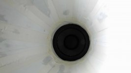
Le Cléac'h petal horn - reinforced this time
So I was thinking about how to reinforce the walls of the horn to determine if they were resonating and causing nulls.
Horn#1 was ruined with previous attempts, so avoid anything with water. Horn#2 was reinforced using paint brushed on hot paraffin wax, with cheap (dollar store) gardening fabric mat. The fabric (plastic?, recylced nylon??) has 1mm grid holes and allows the paraffin to grab and pass through. I get a significantly stiffer walled horn. I just can't go to close to the sun 🙂 Pics below, note the black mat on the back of the horn.
Sadly, there was barely any change in performance, but still worth trying. It's just a bad design combination. It also makes little difference if I go off axis, I get the same dips, for the same reasons.
Attachments
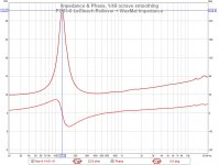
It still is a resonance. What about a standing wave in the back chamber? Did you dampen it in any way?
The rear chamber is 75% filled with fiberglass, the measurement is at Dayton PC83-8 (3") test results so they can be compared. I added a new impedance measurement for this system below.
It has me curious now. I'll try a few things in hornresp, as there is a mismatch in the design somewhere. On the bright side, I can crank out paper horns pretty fast and I don't need to reinforce them for initial testing 🙂
It has me curious now. I'll try a few things in hornresp, as there is a mismatch in the design somewhere. On the bright side, I can crank out paper horns pretty fast and I don't need to reinforce them for initial testing 🙂
Attachments
Last edited:
investigation of Le Cléac'h 7-petal nulls
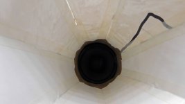
My 7-petal horn#1 seems to have recovered overnight, most of the wrinkles are gone (pre wrinkle pic shown) but the nasty nulls are still there. Time to find out why.
First I tried to see if more or less fibreglass fill was the issue (graph#1). It made very little difference.
Next, I tried to add a polyester fill "phase plug" to the horn to see if the problem was within the horn itself and it made very little difference (graph#2).
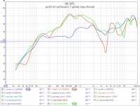
Next, I tried to modify the throat adapter (pics #2, #3). Original adapter is a short cylinder area=31cm^2 and volume=45cm^3. Adapters are difficult for this as the driver frame is a pincushion and the driver can move xmax=2mm. A few trials with modelling clay (pic#3) and we have a solution (graph#3 green curve). The null at 3Khz is gone. There some more work to do, but it looks like the problem is at the adapter.
My 7-petal horn#1 seems to have recovered overnight, most of the wrinkles are gone (pre wrinkle pic shown) but the nasty nulls are still there. Time to find out why.
First I tried to see if more or less fibreglass fill was the issue (graph#1). It made very little difference.
Next, I tried to add a polyester fill "phase plug" to the horn to see if the problem was within the horn itself and it made very little difference (graph#2).
Next, I tried to modify the throat adapter (pics #2, #3). Original adapter is a short cylinder area=31cm^2 and volume=45cm^3. Adapters are difficult for this as the driver frame is a pincushion and the driver can move xmax=2mm. A few trials with modelling clay (pic#3) and we have a solution (graph#3 green curve). The null at 3Khz is gone. There some more work to do, but it looks like the problem is at the adapter.
Attachments
-
 DSCN3052 reduced.jpg341.7 KB · Views: 197
 -
 DSCN3054 reduced.jpg300.7 KB · Views: 206
 -
 DSCN3044 reduced.jpg357.2 KB · Views: 177
 -
 pc83-8 LeCleach 7petal fill option.jpg114.4 KB · Views: 209
 -
 pc83-8 LeCleach 7petal Poly phaseplugs.jpg121.3 KB · Views: 176
 -
 pc83-8 LeCleach 7-petal clay throat.jpg122.7 KB · Views: 188
more fixes to the Le Cléac'h petal horn
I was thinking some more about the 2 nulls and the LF dropoff in the response curve, and what's causing them.
The LF dropoff starting at ~700Hz is from the basic horn design which has a LF cutoff point. The horn's acoustic impedance (Graph #1) drops as shown in the hornresp graph and it becomes less efficient, and output drops <700Hz. The FR returns to the bare driver response, with no horn gain. Graph #2 blue line.
The first FR dip @3.6KHz was found to be the throat chamber (pic#2) which was removed and replaced with a coupling cylinder barely larger that the speaker surround. Graph #2 green line.
The second FR dip@8.8Khz was found to be a phase problem in the horn. This may be an issue with using a cone driver I'm not entirely sure, as I don't have a spare compression driver to compare it to. Adding a makeshift phase plug (pic#3) to the horn eliminated it. I used modelling clay and tried a few shapes until the null was gone. Graph #2 red line. It now has a "saddle" FR shape (>700Hz) that I've seen before in a circular horn.
An interesting side effect is the distortion was lower for freq >500Hz. It looks like it improved, from -50db to -56db THD. The sensitivity went up and the distortion went down. Graph #3.
Attachments
-
 DSCN3085 reduced.jpg308 KB · Views: 271
 -
 DSCN3083 reduced.jpg264.9 KB · Views: 244
 -
 DSCN3084 reduced.jpg362.1 KB · Views: 242
 -
 Pc83-8 LeCleach 11p acoustic impedance.jpg74.8 KB · Views: 302
 -
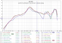 pc83-8 LeCleach 11p throat + phase plug.jpg134.9 KB · Views: 311
 -
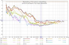 pc83-8 LeCleach 11p t+pp distortion.jpg126 KB · Views: 298
The first FR dip @3.6KHz was found to be the throat chamber (pic#2) which was removed and replaced with a coupling cylinder barely larger that the speaker surround. Graph #2 green line.
Well, you never said anything about having a front chamber. The front chamber basically acts as a band pass and like all filters and almost all cavities it ofcourse also got a resonance.
The second FR dip@8.8Khz was found to be a phase problem in the horn. This may be an issue with using a cone driver I'm not entirely sure, as I don't have a spare compression driver to compare it to. Adding a makeshift phase plug (pic#3) to the horn eliminated it. I used modelling clay and tried a few shapes until the null was gone. Graph #2 red line. It now has a "saddle" FR shape (>700Hz) that I've seen before in a circular horn.
A phase plugs or more, the properties and shapes of it are a science in itself.
Phase Plugs
Thanks @ICG for the link to the phase plug page.
The front chamber was a construction "accident" when I realized the "hat" I put over the pin cushion driver frame was acting like a chamber.
The front chamber was a construction "accident" when I realized the "hat" I put over the pin cushion driver frame was acting like a chamber.
You are clearly having way too much fun. 😉
I also messed around a lot with my Fostex FF85WK. I made ridiculously long foamcore TL's (Nagaoka F81 inspired), conical foamcore front horn, back-loaded "horn". I also toyed with holes along the length of the TL, to see if I could de-Q certain resonant modes, but to no avail, it mostly killed all loading and output, as you seem to have found out. I've also made paper petal horns, but for compression drivers though, 11 segments, painstaking assembly!
Keep it up!
Last edited:
- Home
- Loudspeakers
- Full Range
- Dayton PC83-8 (3") test results