It's only been 2 months since I started posting information, I thought I was doing OK..... seems like I need to step it up 😉
Even though the current testing phase is mostly due to your prompting 🙂
Once these are built it is going to take much longer to get them measured and EQ'd inside due to family restrictions, I apologise in advance to anyone waiting for that 😱
I kind of forgot I wasn't the only one that had to be patient 🙂. Having to wait one whole winter because of circumstances before being able to finish was pretty tough. My build started in ~ April 2013 and wasn't finished until December 2014... Yeah, I was slower 😀.
For me, personally, it all started in September 2011! I bought the drivers in October 2011 (delivery in December of that year) as well as a backup Behringer DEQ2496 (still have it unused in the box). That's when I had made the decision and started to collect the parts for my DSP processing chain even though I had to wait until 2015 to use that part.
wesayso,
Following your journey on the Two Towers was fun and all the updates you've shared, been enjoyable and educational - thank you!
fluid,
Good to progress happening. And smart move on getting the speakers ready before you get to your new (own) place. 🙂
Following your journey on the Two Towers was fun and all the updates you've shared, been enjoyable and educational - thank you!
fluid,
Good to progress happening. And smart move on getting the speakers ready before you get to your new (own) place. 🙂
Ha Ha, I had a table saw and router table where the dining table should have been for 6 months in another house so the arrays are nothing to her 😱
When we get to move into our own home in the near future then things like that probably won't go down so well. One of the reasons I am building these to be unobtrusive 🙂
You better build an onobtrusive workshop near the new house. 😀
I have plans to build a pretty big workshop with a section for drum kits and listening room, although the arrays were destined for the living room.You better build an onobtrusive workshop near the new house. 😀
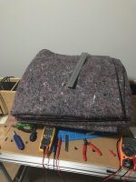
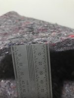
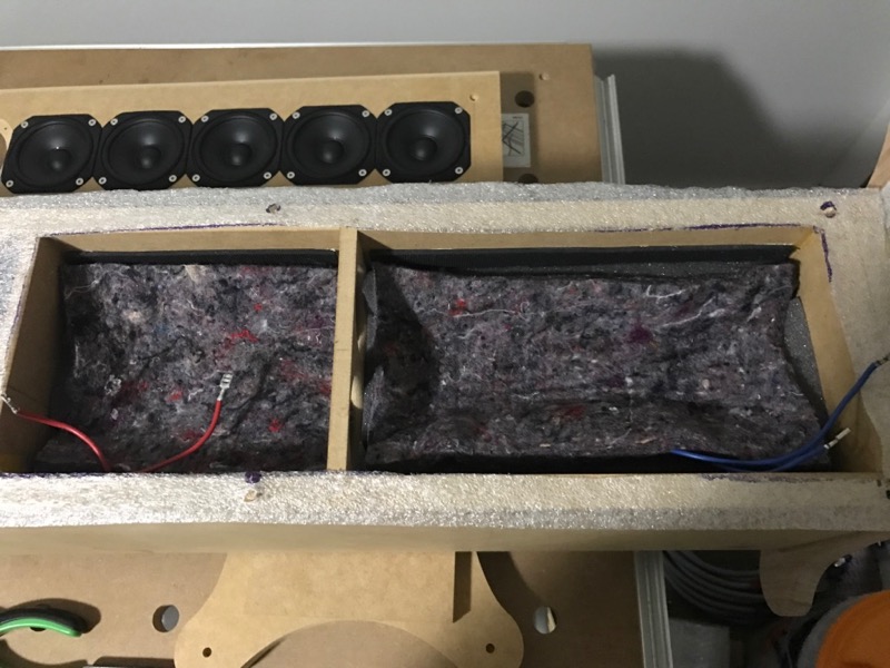
The felt has arrived today and is much better than I thought it would be from the ebay image, about 9mm thick. Now I have some different materials to test.
I haven't set up for impedance testing before so it has taken me extra time to to think about how I will do it with what I have. I have ordered a few things to make a more permanent jig for the future.
Attachments
Felt looks good fluid. By touching it does it feel made of natural materials (recycled denim, wool etc.) or synthetic? It can be a mixture of both too I guess. Measurements and your impressions will be interesting too see.
Drum kits? Sounds like fun! You play?
Drum kits? Sounds like fun! You play?
Felt looks good fluid. By touching it does it feel made of natural materials (recycled denim, wool etc.) or synthetic? It can be a mixture of both too I guess. Measurements and your impressions will be interesting too see.
Drum kits? Sounds like fun! You play?
The felt looks the same I use. I thinks it's a mix of natural and synthetic fibres.
I would agree with gkh that it is not pure wool felt, which I didn't expect. I found a few slivers of what look like shredded foil 😱 Not much of it though. The felt is pretty soft and more natural than I was expecting from the ebay image. It is basically a removalists furniture blanket. I think it will work as I want it to but the measurements will show whether it is any good.
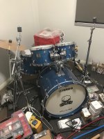
I got my first drum kit at 14, not as flash as this one though! I have converted this to be electric with mesh heads. You can see the cables coming out of the air holes on the toms next to the tom mount. The cheap cymbal is due for a trigger conversion. This is part of the in progress room as you can see from the stuff on the floor 😀 Another room in the house my wife despairs of 😉
Attachments
I got my first drum kit at 14, not as flash as this one though! I have converted this to be electric with mesh heads. You can see the cables coming out of the air holes on the toms next to the tom mount. The cheap cymbal is due for a trigger conversion. This is part of the in progress room as you can see from the stuff on the floor 😀 Another room in the house my wife despairs of 😉
Cool and you are blessed with a tolerant wife! 😀
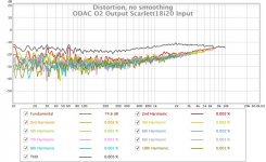
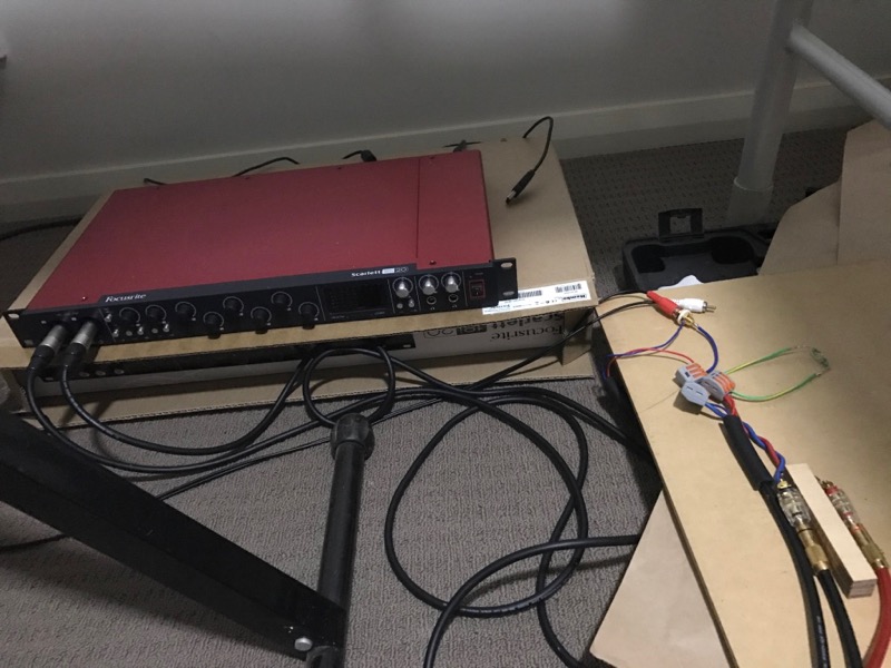
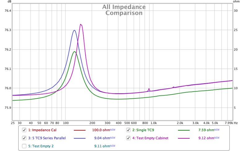
Managed to get my Scarlett18i20 and ODAC O2 headphone amplifier setup to take some impedance measurements. I wanted to use the O2 to have more current available for the impedance tests.
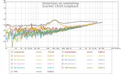
Overall distortion is pretty low 0.003% from a loopback on the Scarlett. The peak in third harmonic at 300Hz is from the Scarlett DA as it not present in the ODAC measurements.
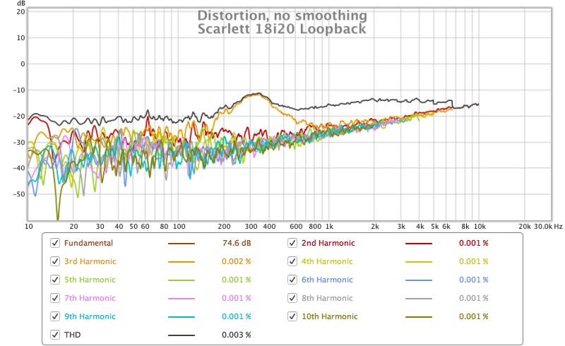
The ODAC O2 is not bad either, working best at full output level in a loopback test 0.005%
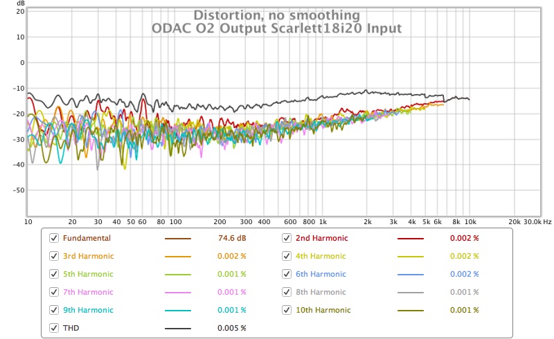
Free air impedance tests resistor used was 100.5 Ohms, I have some lower value ones to try later to see if they affect the results.
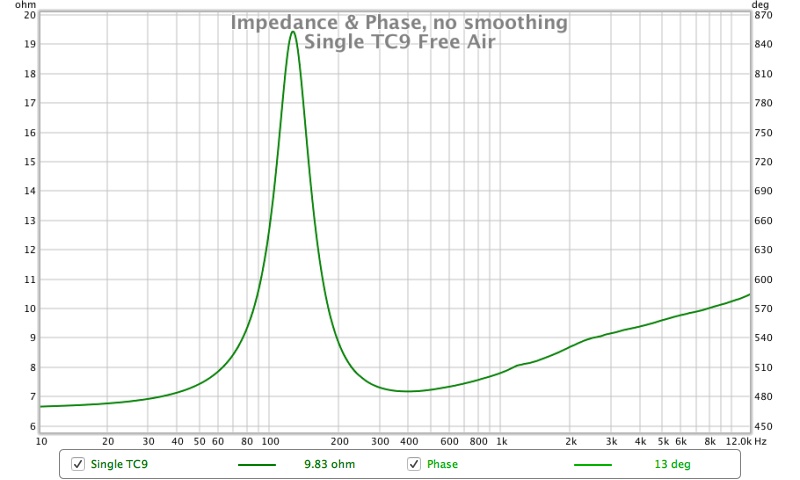
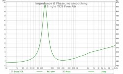
Single TC9
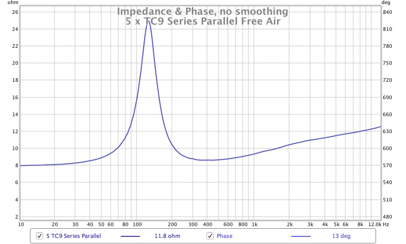
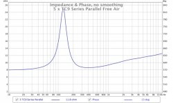
The 5 connected in series parallel (wiring as shown before)
Q calculation made from graph values
Rmax =24.95 Ohms
Rdc 7.896 Ohms
√Rmax x Rdc
√ 7.896 x 24.95 = 14.035 Ohms
F1= 94.75 Hz
F2 = 164.22 Hz
F0 = √F1 x F2
F0 = 124.74
Q = √ Rdc/Rmax x F0/F2-F1
Q=0.7538
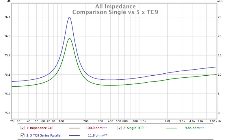
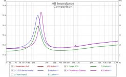
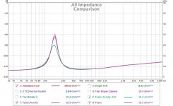
Comparison on the same graph
Overall distortion is pretty low 0.003% from a loopback on the Scarlett. The peak in third harmonic at 300Hz is from the Scarlett DA as it not present in the ODAC measurements.
The ODAC O2 is not bad either, working best at full output level in a loopback test 0.005%
Free air impedance tests resistor used was 100.5 Ohms, I have some lower value ones to try later to see if they affect the results.
Single TC9
The 5 connected in series parallel (wiring as shown before)
Q calculation made from graph values
Rmax =24.95 Ohms
Rdc 7.896 Ohms
√Rmax x Rdc
√ 7.896 x 24.95 = 14.035 Ohms
F1= 94.75 Hz
F2 = 164.22 Hz
F0 = √F1 x F2
F0 = 124.74
Q = √ Rdc/Rmax x F0/F2-F1
Q=0.7538
Comparison on the same graph
Attachments

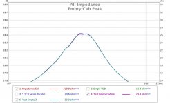
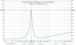
Made an impedance test of the empty bottom chamber in test configuration with 5 drivers.
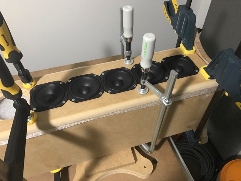
The point to point test version of the impedance jig
Looks like the test structure works as there are no leaks shown in the impedance measurement. A few blips but I think this is pretty good for an empty cabinet with no damping material other than the rubber on the side walls.
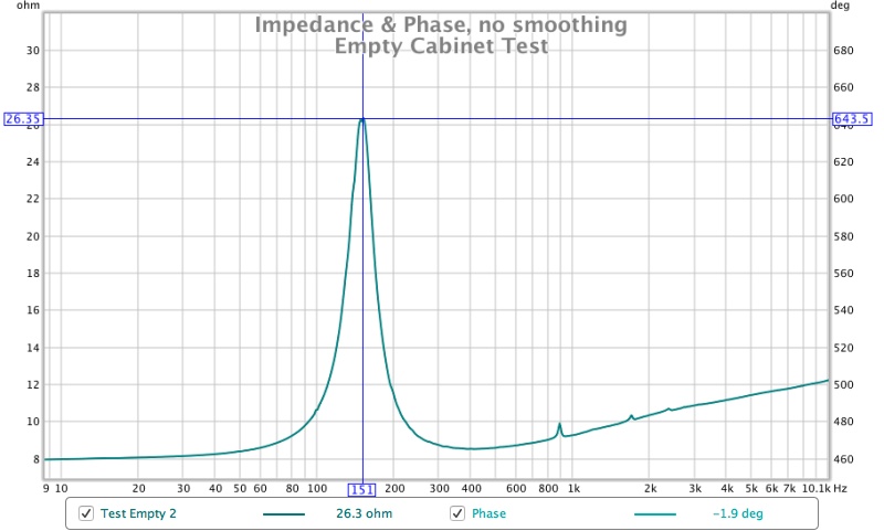
It looks to me that the wiggle at the top of the peak is a measurement anomaly as it moves when the measurement is re-done. I will try some different values of resistor to see if it changes.
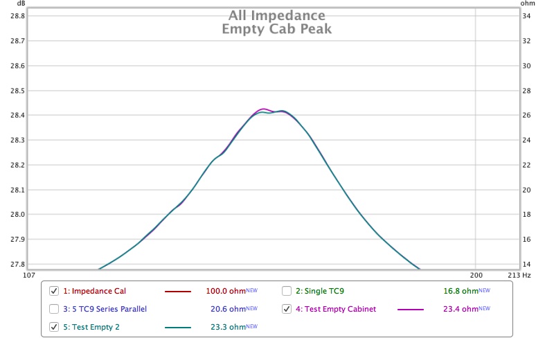
Comparison of Empty cab to free air
Hopefully tomorrow I can get some different damping materials cut up to test.
The point to point test version of the impedance jig
Looks like the test structure works as there are no leaks shown in the impedance measurement. A few blips but I think this is pretty good for an empty cabinet with no damping material other than the rubber on the side walls.
It looks to me that the wiggle at the top of the peak is a measurement anomaly as it moves when the measurement is re-done. I will try some different values of resistor to see if it changes.
Comparison of Empty cab to free air
Hopefully tomorrow I can get some different damping materials cut up to test.
Attachments


Excellent result so far. Looks promising! Smooth out the little blips and you're all set.
Thanks! I decided to follow your lead and know instead of guess 😉
This image from your damping tests is interesting as the same sort of blips are visible, slightly different frequencies but a similar pattern anyway. Perhaps the bigger test chamber I used is responsible. Given the scale on my graph due to the impedance peak I think the blips in mine are fairly minor hopefully the damping will smooth them out.

Mine were with a single driver in a one driver test box test enclosure. The felt will work well (just line the walls) to absorb most of it. Damping the middle of the chamber will help lower the impedance peak (and move it slightly to the left).Thanks! I decided to follow your lead and know instead of guess 😉
This image from your damping tests is interesting as the same sort of blips are visible, slightly different frequencies but a similar pattern anyway. Perhaps the bigger test chamber I used is responsible. Given the scale on my graph due to the impedance peak I think the blips in mine are fairly minor hopefully the damping will smooth them out.
First round of damping schemes have been tested
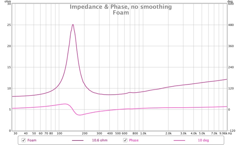
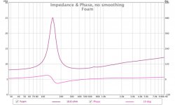
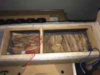
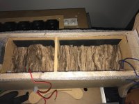
25mm thick egg crate foam on all interior surfaces
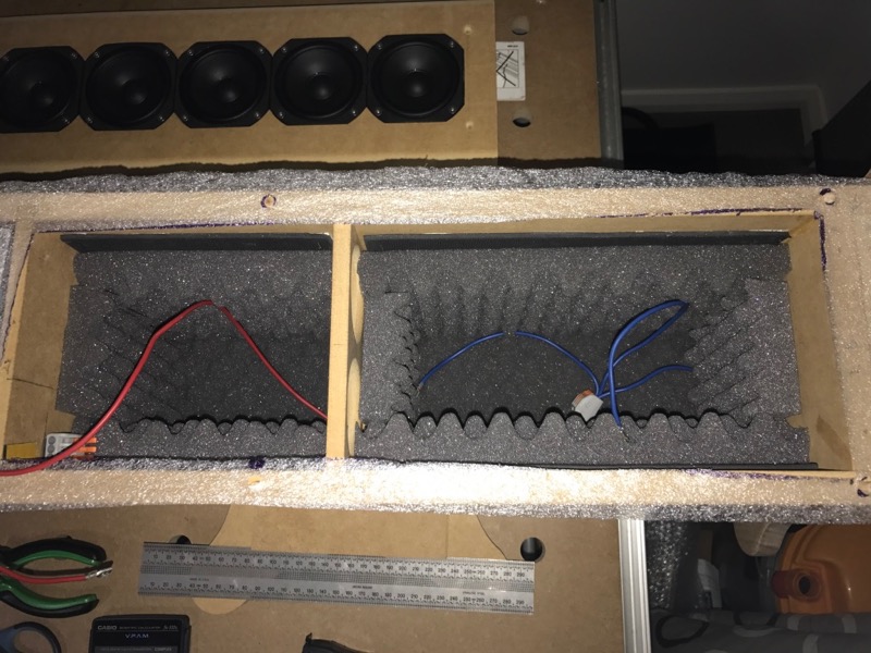
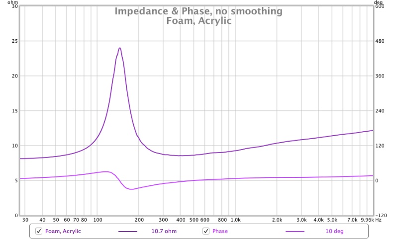
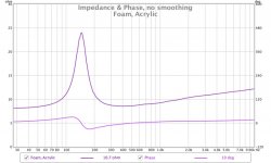
Foam with acrylic damping (Visaton) in the interior space
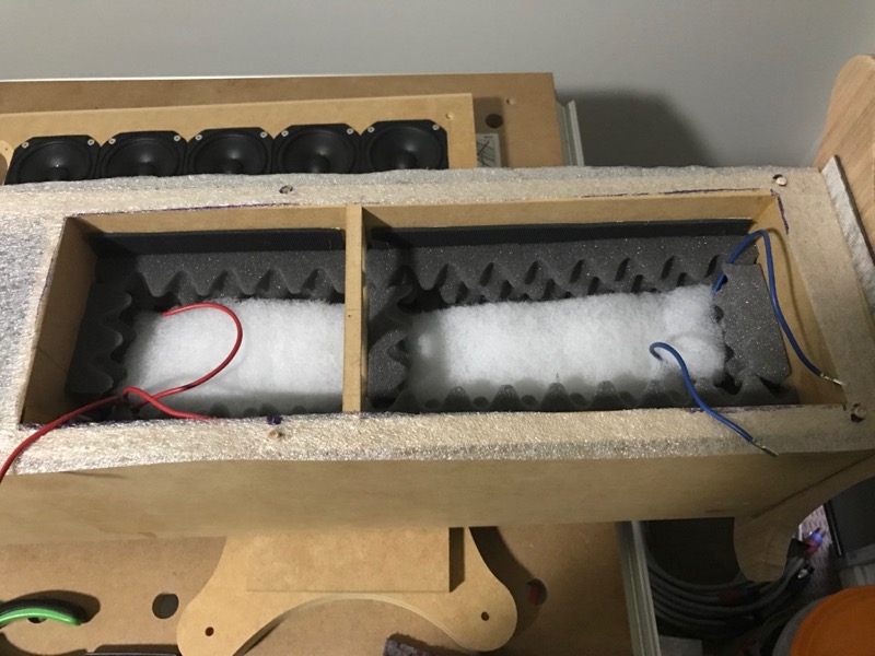
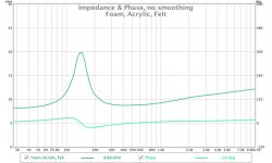
As above but with a piece of felt between the rest and the driver back
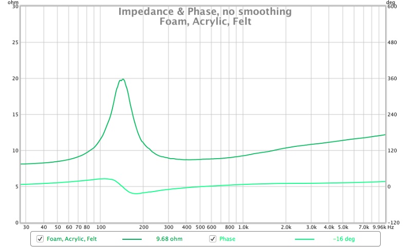
Quick Q calculation on this one gives 0.815, not bad.
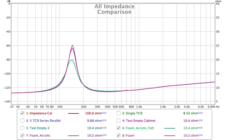
The foam does a pretty good job of damping the blips, the acrylic reduces the peak so it isn't totally worthless, the felt gets rids of almost all the remaining blips and reduces the peak quite considerably.
The next round will be felt on all the walls, fibreglass only and both together.
25mm thick egg crate foam on all interior surfaces
Foam with acrylic damping (Visaton) in the interior space
As above but with a piece of felt between the rest and the driver back
Quick Q calculation on this one gives 0.815, not bad.
The foam does a pretty good job of damping the blips, the acrylic reduces the peak so it isn't totally worthless, the felt gets rids of almost all the remaining blips and reduces the peak quite considerably.
The next round will be felt on all the walls, fibreglass only and both together.
Attachments


Very interesting set of measurements Fluid!
Keep 'em coming 🙂
Your wish is my command 🙂
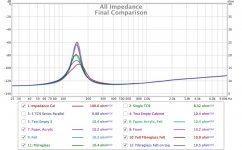
The next set of measurements have a slightly unexpected outcome
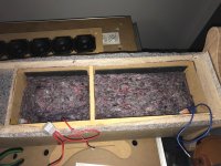
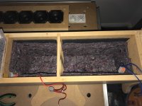
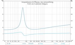
Felt on the cabinet walls only, basically the same as the foam only but takes up less space
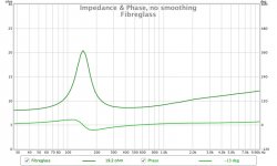
Fibreglass only does a good job of damping the peak down and smoothing out the blips but one is still visible, basically the same as foam felt and acrylic mix.
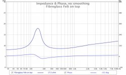
Fibreglass with felt on top, damps the peak even more and the blips are gone Q 0.792
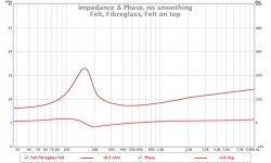
Felt on all the walls, fibreglass fill and felt on top, damps the peak the most but shifts it up in frequency and is now slightly asymmetric Q 0.787 (more unreliable due to asymmetry)
Picture shows how much fibreglass was used between the felt
This one is a bit funky, I'm not sure I like that, perhaps it is overstuffed. If anyone has any thoughts as to why let me know. The only other impedance measurements I have seen similar are Electrostatic panels but the asymmetry is usually the other way.
The comparison shows the overall trend
I am going to try one final mix with felt on the back of the cabinet but not the sides fibreglass fill then felt on top to try and reduce the peak a bit while avoiding the asymmetry.
Attachments
-
 IMG_2590.jpg135.4 KB · Views: 1,813
 -
 IMG_2591.jpg143.1 KB · Views: 1,821
 -
 IMG_2593.jpg129.9 KB · Views: 1,837
 -
 IMG_2589.jpg125.9 KB · Views: 1,837
 -
 Felt Fibreglass Felt.jpg75.5 KB · Views: 1,818
 -
 Fibreglass Felt on top.jpg73.1 KB · Views: 2,187
 -
 Fibreglass.jpg72.8 KB · Views: 1,815
 -
 Felt.jpg72.7 KB · Views: 1,844
 -
 Final Comparison.jpg96.8 KB · Views: 1,803
Interesting results on that last set of measurements.
My assumption (and please keep it at that value of assumption) is that the box is overstuffed, which could explain the peak happening at a higher frequency.
Did you line all the wall depth in felt btw?
The pictures show that felt was applied some 5-10 centimeters shy of the baffle surface.
Do you think that the fiberglass stuffing could be reduced a bit and see how that would affect the measurement?
Fiberglass has been my go-to damping material in TL for many years now, and more often than not, I have had to reduce the amount of stuffing compared to other materials out there.
just my 2cents
N.B: I should probably bite the bullet and procure 50 TC9 drivers to play with.
Leave a bit of air in the back (fiberglass in the middle only), possible with felt all the way in the back. I like the blue one, if it were more symmetrical. Last graph is indeed slightly overstuffed. That will move the peak up again and to the right.
Last edited:
Thanks for the input, seems like my first thought about it being overstuffed is right.
The felt is as seen in the pictures. I could make it go all the way up on the far side but not on the near side because that is where the driver terminals are and some space is needed for those as it is a pretty tight fit already. I was also a little lazy because it meant I could cut a strip the same width from the felt for all surfaces.
I will try with one less piece of fibreglass to see the difference.
Why not build your own the club is expanding 😀 (even though I am not a full member yet due to not having finished... 😉)
That's my next plan to have a piece of felt on the back fibreglass in the middle and felt on the top.
I prefer the blue one too at this point which is the fibreglass with felt on top. I think this one is pretty symmetrical. There is only one degree of phase change between the lower and upper 23 to 22 degrees. The Q calculation of F0 is within 1 Hz of the REW peak reading which is also good confirmation.
This graph has just Fibreglass compared to fibreglass and felt, with single TC9 in free air for reference.
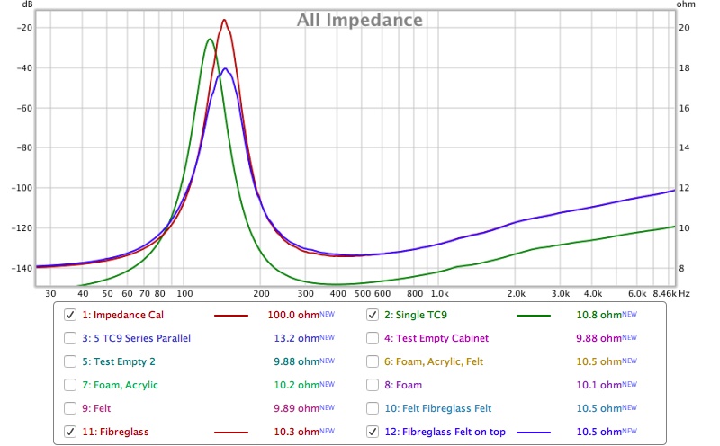
Can you describe where you see the asymmetry
Interesting results on that last set of measurements.
My assumption (and please keep it at that value of assumption) is that the box is overstuffed, which could explain the peak happening at a higher frequency.
Did you line all the wall depth in felt btw?
The pictures show that felt was applied some 5-10 centimeters shy of the baffle surface.
Do you think that the fiberglass stuffing could be reduced a bit and see how that would affect the measurement?
Fiberglass has been my go-to damping material in TL for many years now, and more often than not, I have had to reduce the amount of stuffing compared to other materials out there.
just my 2cents
N.B: I should probably bite the bullet and procure 50 TC9 drivers to play with.
The felt is as seen in the pictures. I could make it go all the way up on the far side but not on the near side because that is where the driver terminals are and some space is needed for those as it is a pretty tight fit already. I was also a little lazy because it meant I could cut a strip the same width from the felt for all surfaces.
I will try with one less piece of fibreglass to see the difference.
Why not build your own the club is expanding 😀 (even though I am not a full member yet due to not having finished... 😉)
Leave a bit of air in the back (fiberglass in the middle only), possible with felt all the way in the back. I like the blue one, if it were more symmetrical. Last graph is indeed slightly overstuffed. That will move the peak up again and to the right.
That's my next plan to have a piece of felt on the back fibreglass in the middle and felt on the top.
I prefer the blue one too at this point which is the fibreglass with felt on top. I think this one is pretty symmetrical. There is only one degree of phase change between the lower and upper 23 to 22 degrees. The Q calculation of F0 is within 1 Hz of the REW peak reading which is also good confirmation.
This graph has just Fibreglass compared to fibreglass and felt, with single TC9 in free air for reference.
Can you describe where you see the asymmetry
Attachments
- Home
- Loudspeakers
- Full Range
- Full Range TC9 Line Array CNC Cabinet