That will be interesting to try. But I'm worrying the coupling between exciter and the bridge is difficult. It's too thin.
I've tried holding an exciter (by hand) and let it drive a foamcore board at its side. There's some sound, but horribly squeaky.
I've tried holding an exciter (by hand) and let it drive a foamcore board at its side. There's some sound, but horribly squeaky.
Perhaps it may be enough to attach the excited to the central portion of the back panel of the violin or cello. Easy to try.
Yes, that'd be much easier. I guess the location of sound post would be the 'sweet spot' 😀
It's very near the HF side of the bridge, must be a good choice to excite.
It's very near the HF side of the bridge, must be a good choice to excite.
..........One thing I can't explain is the bipole character, polarity, and the impulse response.
If it is indeed bipole, the polarity on both sides should be the same. So, it should be no different driven by normal or inverse polarity. But how can we explain the impulse response? -- Very high positive peak and very low negative.
IR look some ala a wideband 3 or 4 way with some point FIR correction , then how does group delay and square waves reproduction look like 🙂 and is it minimum or non minimum phase system
 .
.It would be ideal to have some sort of laser interferometry set up to really develop this sort of driver. That should be the next thing installed in your lab xrk, and CLS too... 🙂
However, I have a low tech solution: get out the glitter and a signal generator.... It will readily detect chladni patterns.
In theory, the goal should be an expanding wave with an origin at the motor that matches the expansion of a spherical wave formed in the air. Essentially, you want a mechanical Quad ESL. Assuming a large flat panel forming a hemispherical radiation, the sound should travel through the panel at the same speed as the air at 'normal' temp and pressure. The wave speed should constant at all frequencies -- which as a requirement is a doozy.
Needless to say, virtually any bell resonances are going to be distortion. In practice, I'm not sure it's possible to avoid them.
Possibly the worst allegedly hifi speaker I've ever heard was a flat panel driver with a foam core diaphragm, but it would be interesting to see if this sort of thing could be done well. Sounds like CLS has been experimenting for a while, and has gotten some results.
In theory, the goal should be an expanding wave with an origin at the motor that matches the expansion of a spherical wave formed in the air. Essentially, you want a mechanical Quad ESL. Assuming a large flat panel forming a hemispherical radiation, the sound should travel through the panel at the same speed as the air at 'normal' temp and pressure. The wave speed should constant at all frequencies -- which as a requirement is a doozy.
Hi,
In practise distributed mode loudspeakers don't work like that at all.
The operation is entirely different, and your missing the point entirely.
rgds, sreten.

You could lay the panel flat, put Some sugar on it and look at the Patterns when you play sines at different frequenties. This way you can see were the effectieve placets are to place the blobs for certain frequenties.
Fun!
I think sand may be a bit cleaner than sugar, and black foam core board may be ideal. They do something similar to visualize drum head modes.

An externally hosted image should be here but it was not working when we last tested it.
You don't want to lay it directly on floor either - suspended at edges with frame or strings.

...
Possibly the worst allegedly hifi speaker I've ever heard was a flat panel driver with a foam core diaphragm, but it would be interesting to see if this sort of thing could be done well. ....
The operating principle of DML is simple, however the methods of implementations are varied a LOT, so are the results.
Not many commercial products out there. Here are some of them:
Podium
Teragaki-Labo?????????????????TERRA???????????
Ciresa Opere Sonore : enceintes plates en bois d'instruments
http://www.commbax.com/products/minipro/images/minipro.pdf
Professional Distributed Mode Loudspeakers |
I guess it's because of the special acoustic features, it's gradually showing up in pro audio. There must be some pro audio shows where you can see and hear them.
freddi,
Nice find!
It's said thin plywood (3mm) is a good material for panel. I haven't try it.
I've tried my desk in office which is thick particle board. It's too heavy. Lighter material would be more efficient.
Nice find!
It's said thin plywood (3mm) is a good material for panel. I haven't try it.
I've tried my desk in office which is thick particle board. It's too heavy. Lighter material would be more efficient.
if we knew how well it would work, for those in the US, it would be around $23 shipped for two 24"x30" pieces of 3mm Baltic birch - 30x48 might be good
http://www.amazon.com/Single-Piece-...d=1428456753&sr=8-1&keywords=3mm+baltic+birch
http://www.amazon.com/Single-Piece-...d=1428456753&sr=8-1&keywords=3mm+baltic+birch
freddi,
Nice find!
It's said thin plywood (3mm) is a good material for panel. I haven't try it.
I've tried my desk in office which is thick particle board. It's too heavy. Lighter material would be more efficient.
We have lots of mom and pop shops here selling up to 4x8 panels of thin ply. That was my first thought when I first saw the DML threads...
I think 4x8 Sureply luaan plywood used for sub floors might be an alternative. 3/16in thick I think.
Always on the lookout for esoteric new ideas to try myself, I wondered what "DML" means. OK, I've read the entire thread and now I know 🙂 So far my experimentation consists of dissecting a spare Selenium tweeter (easy), glueing five pennies in a stack to its voice coil (Gorilla Glue, of course) and to a coroplast board and ... to be determined. Not quite full range. DML does "sound" 🙂 like a cool idea. Isn't this similar to Poly-Planar, a product from the 1970s, I believe?
Why the pennies? To bring fs down? Take an old cheap full range driver like the ones in PC speakers and cut spiders into the cone to vent it. Add a hard plastic or cardboard puck glued to the voice coil or dustcap so that it extends out. If surround doesn't bump up, glue bezel and puck to your panel (or use double sided tape). Otherwise add a ring of foam core to the bezel to elevate before gluing to panel. Now you have a full range exciter or transducer for a DML.
The pennies was a 5x stack to connect the voice coil to my panel. I had read one of the Walsh threads and I think it suggested a tweeter. Also this was the most readily avaiable victim 🙂
Also, to construct a Walsh type driver is a bit more involved than the exciters. I apparently don't have any diamond or carbon nanotube foil on hand 🙄 not to mention the fine assembly skills required.
XRK, thank you for the suggestion. I looked at a "normal" driver (actually a 12" woofer) and it looked like it would require cutting off the metal basket and removing the cone. Perhaps your method will work...I just need to envision it a bit first.
Now, off to the closet to look for a suitable victim to experiment upon
Same here! I have a couple of cheap $3 3" drivers, and I'm trying to figure out the steps to turn it into a transducer... Got a picture!? 😉
Same here! I have a couple of cheap $3 3" drivers, and I'm trying to figure out the steps to turn it into a transducer... Got a picture!? 😉
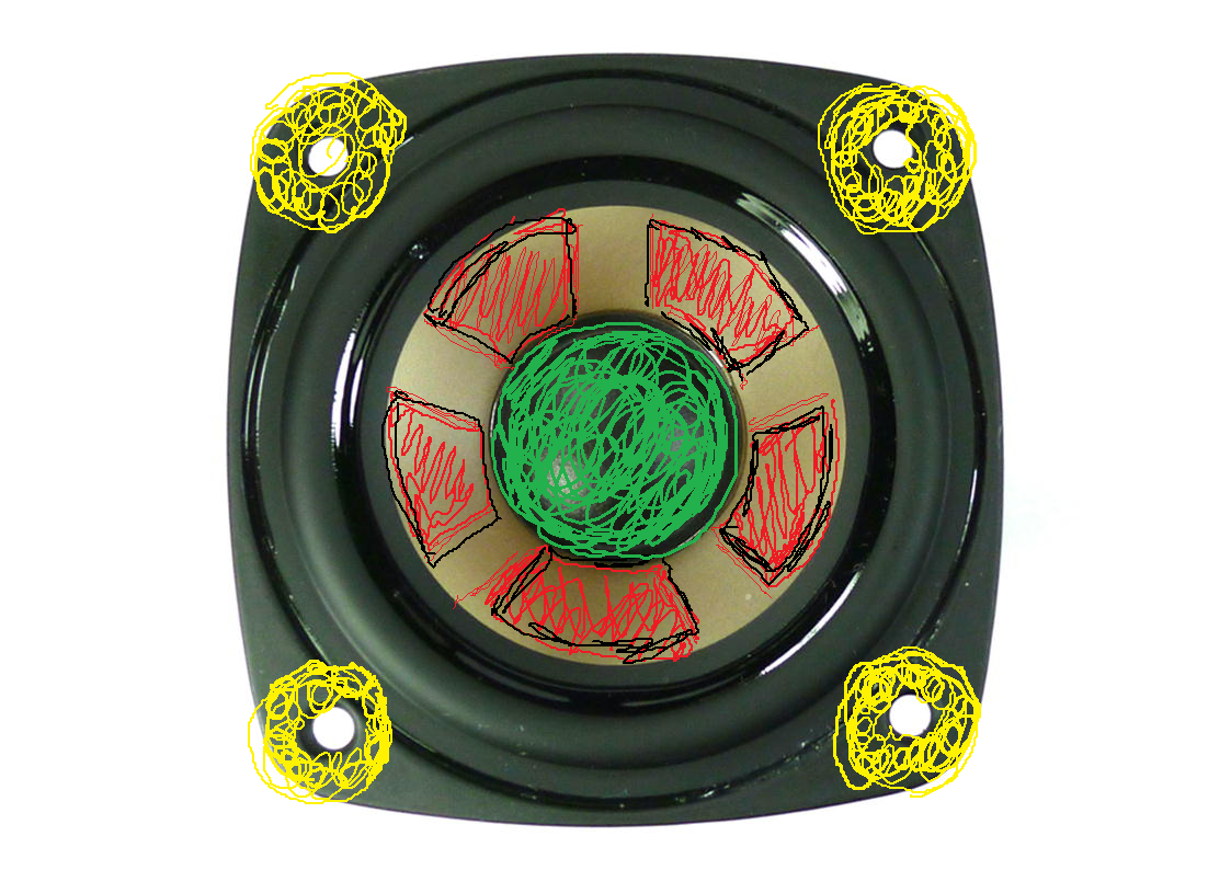
I haven't actually done this yet - but here is my plan:
1. Cut out the (red) colored sections of the cone to make a 5-arm suspension spider.
2. Add layer of wood or plastic standoffs where mounting screws go (yellow) by gluing (hot melt) plastic washers or wood washers/discs to elevate bezel to allow surround to move without touching panel.
3. Add a round hard plastic or wooden disc (green) or puck that fits over the voice coil and dustcap - needs to be stiff to transmit pressure from voice coil.
On a side view, the standoffs (yellow) need to be flush with puck (green) and have sufficient clearance for x-limit movement (usually more than xmax). The idea is to have the cone cutout to remove the ability of the cone to act as a sound radiator but still provide suspension attachment to the basket/bezel.
Either use glue or double sided tape to stick the standoffs and puck to the panel. Note that this works fine for smaller lightweight drivers (3in and under with light magnets). For larger drivers with heavy magnets, an external support structure for mounting the driver basket and magnet to an external frame that supports both the panel and driver is needed.
Here is a sketch of a typical 3in polycone driver that can be cut as described above:
Attachments
My thinking is similar but I work with Gorilla Glue and empty cat food cans. 😹I am using a 12 inch woofer and I gorilla glued an inverted can to cover the voice coil. I am leaving the cone uncut for the time being. My thinking is this: depending on how much space you have with this the standoffs or spacers, the cone radiating sound may not be an issue. Consider that when voice coil transmitting the force to the surface, this will reduce cone displacement. I can fillet the cone later 😛
- Home
- Loudspeakers
- Full Range
- A Study of DMLs as a Full Range Speaker