Probably not a bad idea to start your own thread about it. No problem though to ask these questions.
Do research what Danley has to offer, it has been designed for the purpose you're after and most if not all of his solutions are pretty well thought out.
Not that it's easy to copy what he does, the paraline in particular has been copied a lot by DIY enthusiasts, but not that many were successful.
If you start the thread, include pictures of the church to help with ideas. I immediately have pictures in my mind by reading that word, but that doesn't have to be an accurate representation of your particular environment.
Basically you want to minimise reflections and indirect sound coming back by having directivity and coverage where you want it. Vertical directivity is covered with arrays, but as said, the horizontal coverage might need help too. If it's a really big space some repeat speakers properly delayed might work better to get good overall coverage. I bet if you search for it on these forums there will be similar threads already.
Back to line arrays then....
I loved my no frills line arrays of 16 drivers per tower, the wall of sound they created was impressive in both music and movies.
Having had the opportunity to build some open baffle, I love the ambiance and the pin point accuracy that OB brings.
So..... why not combine the two?
Open baffle line arrays. Has a nice ring to it! I like how those four words sound! And I'm sure the sound coming from that would probably be very nice as well.
I've been reading a bit, like this guy: Open Baffle Line Array Speakers
And I am drawn to try an open baffle line array system.
Any thoughts? Suggestions? Warnings?
Why not an array like Nola Brio Trio? Each pair of drivers can be 1.5 way combo of dipole and sealed.Back to line arrays then....
So..... why not combine the two?
Any thoughts? Suggestions? Warnings?
Why not an array like Nola Brio Trio? Each pair of drivers can be 1.5 way combo of dipole and sealed.
That would be a wiring nightmare, just for starters.
If it's 25 drivers each tower, than could do the 5 bottom and the 5 top drivers sealed, and the 15 drivers in the middle OB....
Or the opposite, 5 drivers top and bottom OB and the 15 middle drivers sealed.
I have no idea if it would produce the same cardioid effect as the Brios.
Back to line arrays then....
I loved my no frills line arrays of 16 drivers per tower, the wall of sound they created was impressive in both music and movies.
Having had the opportunity to build some open baffle, I love the ambiance and the pin point accuracy that OB brings.
So..... why not combine the two?
Open baffle line arrays. Has a nice ring to it! I like how those four words sound! And I'm sure the sound coming from that would probably be very nice as well.
I've been reading a bit, like this guy: Open Baffle Line Array Speakers
And I am drawn to try an open baffle line array system.
Any thoughts? Suggestions? Warnings?
If you avoid early reflections (internal and external) and diffraction, sealed can do what you want.
The open baffle performance will depend on baffle size for it's dipole peak.
For me the beauty was in a full range signal all from the same line.
Open baffle couldn't do that, the "no box sound" of open baffle is often highly praised. With care, sealed boxes don't have to have a box sound.
FIR filtering, and especially the length of that filtering on the top end made a difference for me in the amount of pin point accuracy perceived.
Points that are important for imaging:
- left/right balance
- no early reflections
- identical phase left/right (which means, really no early reflections)
Notice I didn't say linear phase, just identical.
The line source has the advantage of avoiding the floor and ceiling reflections. If you build an open baffle line array, it might not extend low enough to have that benefit. Unless you combine it with a line array for the low end.
Subs wouldn't have that same benefit, that much is sure.
For me, I feel that's the biggest difference between the "they are here"/"you are there". The avoidance of the floor/ceiling reflections (of course also 'removing' the other early reflection/diffraction is part of the pré-requirements)
If you're going open baffle and line array, meaning not using the bottom end... take a look at this build: http://www.diyaudio.com/forums/planars-exotics/301091-diy-planar-magnetic-open-baffle-woofer-array.html
A true line source would be hard to beat. The current last pages do show some near field IR and STEP responses that are mighty convincing. No FIR filter was used. Still waiting how it looks from the listening position.
Last edited:
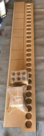
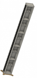
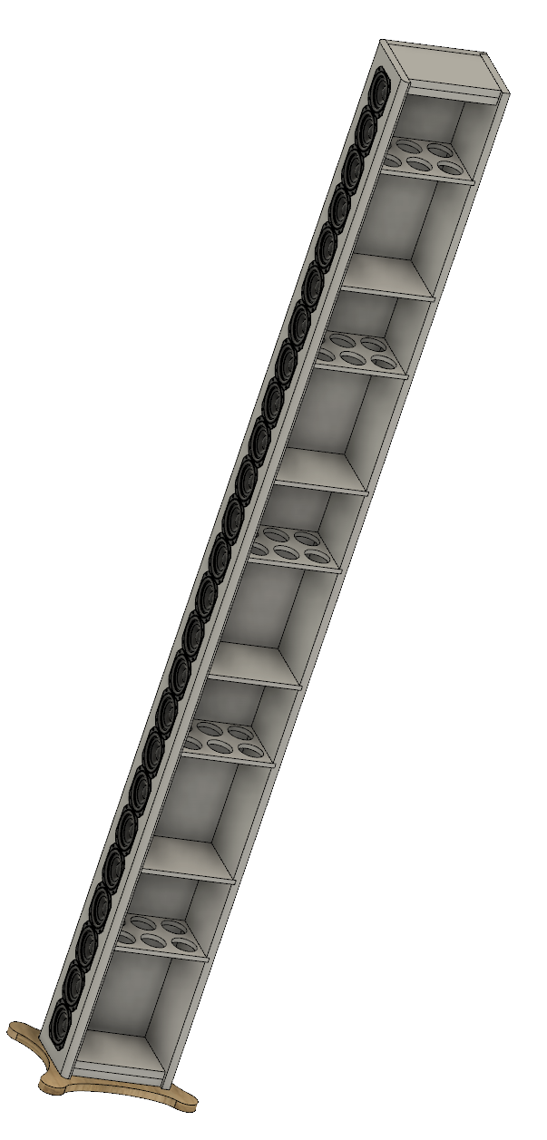
I had a visit from the CNC Fairy today, I will start a new thread to document the build but this is as far as I have got for now. Fingers crossed I got the CAD design right...


Cool! CNC Fairy's are good, much better than a hand router!

We do have big a$$ eq unit and I guess there is option to add "delay" too IIRC. There are lot of sliders and knobs
And yeah, the eq. has been tuned by a sound engineer for our church already but its not working for all voices !
I'm sorry for this OT talk !
May be I should create a new thread
Once upon a time I did Pro Audio sound systems to the likes of Charlotte Coliseum, Peace Center for Performing Arts, etc. In that vast job requirements were Churches. Billy Graham's The Cove to name one. Many had line arrays, none as long as Ronalds but none the less say they for the most part were very crappy sounding. They had racks of EQ, delay, etc. None of which were properly setup. One tool in the vacuum of test/setup equipment was an Ivie IE30b handheld spectrum analyzer. That was the best we had
I argued for more/better, but was always shot down due to cost and the ignorance of the use of better, questionable gains of such. Management wouldn't budge. Sigh.
As mentioned EQ would help with the aid of a calibrated mic and Room Equalization Wizard (free). Proficient use of these two items can take you quite far in resolving your churches issues. I will add that today a miniDSP DRC/DIRAC Live is well within the budget of any church. How to implement is another science that must be mastered before going "live". Learn these and most all problems will disappear with the current equipment / speaker systems in place most likely. Cost to implement should be below $2k, a price the Elders should have no problem with.
Take it upon yourself to master and you'll be applauded.
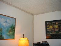
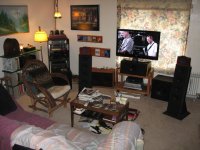
With all the talk about high end digital processing (which I have very limited experience with) I didn't think I'd have anything else to contribute that would help here. But I do. My living room which is fairly typical, rang rather significantly when I would clap my hands and listen. That's with a large sofa, several bookshelves, and all the usual stuff. So I nailed 2 inch diameter cotton rope, bought at a fabric store, into all corners above the floor, and I was surprised at how well that reduced the ringing when I would clap my hands and listen. So my advise is, don't do that... it turns out that cotton rope is VERY flammable. Instead I recommend a few inches of foam rubber, especially in the 3 surface corners. Auralux is one brand (in the U.S.) that makes such stuff and it has the fire retardant in it. You attach it with a glue that is hopefully fully removable in case you ever want to sell the house. But I highly recommend trying that. The cotton rope was very inexpensive, so you could try it with that, and then swap it out with something safer.
Attachments
Personally like cotton rope, regardless of how flammable it is. The real problem with foam even the likes of Auralux is that despite having a flame retardant, produces an even bigger problem, noxious and toxic fumes.With all the talk about high end digital processing (which I have very limited experience with) I didn't think I'd have anything else to contribute that would help here. But I do. My living room which is fairly typical, rang rather significantly when I would clap my hands and listen. That's with a large sofa, several bookshelves, and all the usual stuff. So I nailed 2 inch diameter cotton rope, bought at a fabric store, into all corners above the floor, and I was surprised at how well that reduced the ringing when I would clap my hands and listen. So my advise is, don't do that... it turns out that cotton rope is VERY flammable. Instead I recommend a few inches of foam rubber, especially in the 3 surface corners. Auralux is one brand (in the U.S.) that makes such stuff and it has the fire retardant in it. You attach it with a glue that is hopefully fully removable in case you ever want to sell the house. But I highly recommend trying that. The cotton rope was very inexpensive, so you could try it with that, and then swap it out with something safer.
Halon is an awesome fire suppressant, but what the average person doesn't know it that when exposed to fire or even extreme heat produces Phosgene gas. It is 100 times more damaging to the atmosphere compared to CFC's aka Freon.
Funny: when I was a kid launched Estes rockets. Between the engine and the recovery system, be it a streamer or parachute required a flame resistant wadding. Estes was all to happy to sell 6 squares to you for a premium. It was nothing more than toilet paper. My own flame tests proved that beyond a shadow of a doubt. For the price Estes wanted I could get 6 rolls of Charmin and that was even handier in the field, behind the bushes
Actually I'm still a kid, just doing it with another generation
Last edited:
Very good point about the out-gassing of fumes from foams and the contact cement like glue that holds the pieces to the walls. I've got a couple boxes of Auralux foam in my attic, and 10 years later I've still got the 2 inch cotton rope nailed into the corners of my living room... I just felt that I should warn people in case anyone gets the cotton rope too near a heat source.Personally like cotton rope, regardless of how flammable it is. The real problem with foam even the likes of Auralux is that despite having a flame retardant, produces an even bigger problem, noxious and toxic fumes.
Halon is an awesome fire suppressant, but what the average person doesn't know it that when exposed to fire or even extreme heat produces Phosgene gas. It is 100 times more damaging to the atmosphere compared to CFC's aka Freon.
Everybody knows about comb filter effects from wall, floor or ceiling bounce, but it seems that few realize that corners are like acoustic amplifiers or resonators. Just that relatively tiny 2 inch cotton rope made an obvious difference in room ring with the clapped hand test. If I wasn't busy/lazy, I'd put the 12 inch "aged" Auralux foam cubes in the 3 surface corners. Maybe my 10 year old foam is about done out-gassing by now.
I still have some ideas to try and better my performance, apart from adding subs.
But lately I just can't stop listening. Part of it is the knowledge I can't run tests for days anymore. So I'd have to be very efficient in one day or come up with the patience to spread it out over a couple of weeks.
It's been months since I last brought out my measurement gear. I probably would have brought it out sooner if I wasn't this pleased with the sound I have.
But lately I just can't stop listening. Part of it is the knowledge I can't run tests for days anymore. So I'd have to be very efficient in one day or come up with the patience to spread it out over a couple of weeks.
It's been months since I last brought out my measurement gear. I probably would have brought it out sooner if I wasn't this pleased with the sound I have
.Cool! CNC Fairy's are good, much better than a hand router!
You have shown that a hand router can produce great results when given enough time and effort. It hurt a little to pay someone else to CNC the cabinets to my design but when they arrived I realised just how much time it would have taken me to do myself and I likely would have chosen a different method to make the work easier.
I made a 3D model and used your 3D TC9 to do a sanity check and all looks to fit together nicely.
Attachments
It's been months since I last brought out my measurement gear. I probably would have brought it out sooner if I wasn't this pleased with the sound I have
Good man, just enjoy the music...!
You have shown that a hand router can produce great results when given enough time and effort. It hurt a little to pay someone else to CNC the cabinets to my design but when they arrived I realised just how much time it would have taken me to do myself and I likely would have chosen a different method to make the work easier.
I made a 3D model and used your 3D TC9 to do a sanity check and all looks to fit together nicely.
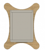
I did see a finished CNC-ed baffle. Do the real drivers fit?
If you can, I'd definitely look at ways to chamfer the sharp edges on the sides. These will be something in common for each driver, thus it will not be averaging out by using many drivers. You'll get diffraction from those sharp edges, how severe it will be I cannot tell you. Though every little bit we can do to avoid it does help.
Duhh... I must be blind. Upon second gaze I do see a round-over, though a relatively small one. It will still help avoid some of that diffraction.
Your drivers are even more closely packed than mine. Good! I still have "some" space between them. If you fill the chamber with damping, be sure to use impedance curves as a guide. Look for the smoothest curve possible. Every bump in that graph is a potential FR problem.
Especially with the TC9 as it's very well behaved when measured without an enclosure.
I can recommend real wool felt on all walls, fiberglass insulation as damping material and a layer of felt between the fiberglass and the back of the driver. I still have some open space behind each driver. The wool felt definitely helped to get better results vs Fiberglass fill only.
Only in hindsight I noticed 25 of these drivers were having the impedance peak very close to the baffle length. Meaning my 2.25 M tall baffle is very close to the ~150 Hz the total impedance landed on. So be sure to fasten the baffle in a non symmetrical way, not divided in 2 of 4 or 8 but at 3, 5, 7 etc. places... I ended up damping the baffle/enclosure + O-rings on mounting screws which cured an irregularity in the impedance.
Your drawing has that uneven number plus the out of sync in-between support which should help.
Last edited:
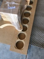
I did see a finished CNC-ed baffle. Do the real drivers fit?
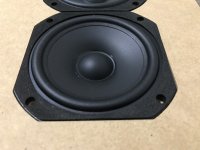
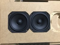
Until you asked that question I hadn't checked, I have now and they are a perfect fit
Just enough extra space to be able to get them in and enough depth in the recess to allow some gasket tape to bring the plastic basket flush with the baffle. Duhh... I must be blind. Upon second gaze I do see a round-over, though a relatively small one. It will still help avoid some of that diffraction.
There is a 1/2 inch roundover on the front baffle in the model but the actual baffle is still square as that will need to be done manually after the cabinet is assembled. A Top down view should make it more obvious. The features of the model tend to get obscured in the screen grabs wen you need to get the whole line in.
The part that is not shown in the model is my plan to reduce edge diffraction by using pressed wool felt on the baffle similar to a Dunlavy approach. The added benefit is that it will allow a bit of space for excursion as I plan to wrap the line in a fabric sock like OPC except mine will be black.
Your drivers are even more closely packed than mine.
I can recommend real wool felt on all walls, fiberglass insulation as damping material and a layer of felt between the fiberglass and the back of the driver. I still have some open space behind each driver. The wool felt definitely helped to get better results vs Fiberglass fill only.
The drivers are mounted frame to frame so there really is no space between them!
I would love to use wool felt but the prices of it here are too high. The 4.8mm baffle felt cost me enough. I got some fibreglass insulation at a really cheap price so that will form the bulk of the stuffing and I will probably wrap it in the white polyester that I also have. I have a sheet of 3mm rubber that I might use to line the inside walls with in an attempt to get some CLD. It will be a lot of effort to cut the rubber so it may get dropped.
I am trying to get the best result I can while still being efficient with my time and resources so I doubt I will get to all the tweaks you did, but they are guiding me on where best to put the effort.
Only in hindsight I noticed 25 of these drivers were having the impedance peak very close to the baffle length. Meaning my 2.25 M tall baffle is very close to the ~150 Hz the total impedance landed on. So be sure to fasten the baffle in a non symmetrical way, not divided in 2 of 4 or 8 but at 3, 5, 7 etc. places... I ended up damping the baffle/enclosure + O-rings on mounting screws which cured an irregularity in the impedance.
Your drawing has that uneven number plus the out of sync in-between support which should help.
There will actually be 5 separate sealed enclosures as the solid braces will be glued to the baffle. The entire cabinet was designed to be glued together to form a rigid structure so it won't be fastened at specific points. The Dado's and the faces will be glued and clamped along their entire length.
I suppose time and impedance measurements will tell
Attachments
I can perfectly understand looking for ways to save time .
I think the rubber would be a nice touch. You might want to play with automotive damping, though the aluminium layer will not help with damping.
I got me a huge wool felt roll at a very attractive price. I had seen huge prices everywhere but bumped into someone selling wool for isolation purposes.
I'd imagine there are lots of sheep in Australia. My wool came from France.
My final radius was about 1" gradually transitioning into the side curve:

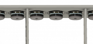
Be sure to look into the points where the braces are between drivers, with the drivers packed that close you don't want to limit the back wave opening. I used a piece of MLV in the opening as to keep as much airflow as possible. I also used that side to wire up the drivers.

The side that didn't have connectors was just trimmed down to keep the airflow. Playing with felt there helped alleviate impedance bumps.
.I think the rubber would be a nice touch. You might want to play with automotive damping, though the aluminium layer will not help with damping.
I got me a huge wool felt roll at a very attractive price. I had seen huge prices everywhere but bumped into someone selling wool for isolation purposes.
I'd imagine there are lots of sheep in Australia
. My wool came from France.My final radius was about 1" gradually transitioning into the side curve:
Be sure to look into the points where the braces are between drivers, with the drivers packed that close you don't want to limit the back wave opening. I used a piece of MLV in the opening as to keep as much airflow as possible. I also used that side to wire up the drivers.
The side that didn't have connectors was just trimmed down to keep the airflow. Playing with felt there helped alleviate impedance bumps.
I can perfectly understand looking for ways to save time
I think the rubber would be a nice touch. You might want to play with automotive damping, though the aluminium layer will not help with damping.
I got me a huge wool felt roll at a very attractive price. I had seen huge prices everywhere but bumped into someone selling wool for isolation purposes.
I'd imagine there are lots of sheep in Australia
Plenty of Sheep here but there are very few felt sellers and the only one in my state was expensive. There is a rougher version used for furniture blankets by removalists, I should have asked for one of theirs the last time I moved
The problem I have with most items like this is the shipping cost as I live in a regional area most items have to be shipped and due to the physical size the cost is too much.
My final radius was about 1" gradually transitioning into the side curve:
I thought very hard about getting CNC cut ply but cost and complexity was too much.
Be sure to look into the points where the braces are between drivers, with the drivers packed that close you don't want to limit the back wave opening. I used a piece of MLV in the opening as to keep as much airflow as possible. I also used that side to wire up the drivers.
The side that didn't have connectors was just trimmed down to keep the airflow. Playing with felt there helped alleviate impedance bumps.
The braces are only 9mm thick so they don't take up too much space, the strength comes from being sunk into the cabinet and glued together.
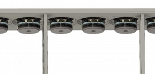
I am deciding whether to chamfer the back of the magnet cutouts, a 4mm chamfer looks like this.
I have mounted the drivers with the terminals to one side as with them on the bottom they interfered with the top and bottom plates.
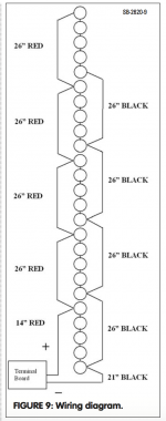
I'm planning to wire mine like this from Roger Russell's Audioexpress article. I've got some knock off Wago wire lever clamps to use where the wires are joined to avoid having to run multiple lengths of wire up and down the cabinet.
Attachments
- Home
- Loudspeakers
- Full Range
- The making of: The Two Towers (a 25 driver Full Range line array)