Hi jackinnj
What about one more hole to use a metal standoff to ground to a metal plate/can?
Duke
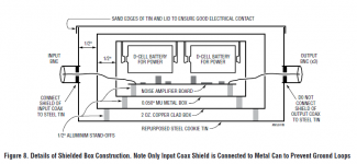
From Linear Tech ApNote 159:
Attachments
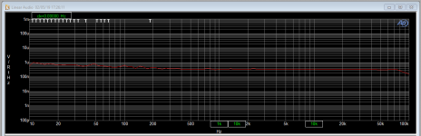
Finally got around to measure Samuel's LNA powered by a Silent Switcher with the AP. Confirmed 350pV/RtHz.
I also have a Brookdeal 431 nanovolt preamp, running on batteries, specced at 400pV/RtHz and also confirmed.
Both 60dB gain but the Brookdeal has switchable roll-off at either side of the frequency range and two different input impedances (6k and 15k).
Nice to have some baselines. ;-)
Jan
I also have a Brookdeal 431 nanovolt preamp, running on batteries, specced at 400pV/RtHz and also confirmed.
Both 60dB gain but the Brookdeal has switchable roll-off at either side of the frequency range and two different input impedances (6k and 15k).
Nice to have some baselines. ;-)
Jan
Last edited:
Hello,
First of all:
is there a source for spare pcbs for this amplifier?
I tried to upload the gerber files from nanovolt.ch to the maker-pcb manufacturers oshpark and aisler, but it did not work properly. I always got error messages.
Eventually their auto import feature does not work with complex gerber files, or have to make some adjustments first... Does anybody have experience with manufacturing these pcbs? Are there some recomendations where to go to? I‘m located in Germany. Thanks
Hello,
First of all: is there a source for spare pcbs for this amplifier?
I tried to upload the gerber files from nanovolt.ch to the maker-pcb manufacturers oshpark and aisler, but it did not work properly. I always got error messages.
Eventually their auto import feature does not work with complex gerber files, or have to make some adjustments first... Does anybody have experience with manufacturing these pcbs? Are there some recomendations where to go to? I‘m located in Germany. Thanks
I had some boards recently made at PCBway. That worked out quite nicely. Only problem was German customs in Leipzig who would not believe that the production of 10 boards costs $5 + transport. They gave in when I sent them the URL of PCBway orderering and proposed that for $5 + transport they could have their own shiny circuit boards. It seems they had no interest, but it did the trick.
")
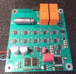
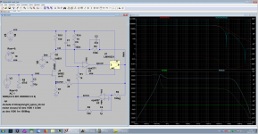
One of these was a respin of my 220 pV/rtHz preamp. It has now a 2nd input with a AD8620 for browsing with a scope probe; that gives away most of the noise advantage but is convenient and the low pass filter may help. Gain, low pass frequency corners, input selection and protection relays are now controlled with analog switches that are set up by a $2 CPLD that has a opto-coupled SPI-interface to the external world. It is also possible to use mechanical switches instead.
There will be a $5 board respin to remove a bug for the 80 dB gain selection and also an unexpected and intolerable noise increase from 220 pV/rt Hz to 400 pV/rt Hz above 500 KHz. I first had the idea that this was a peaking effect but it wasn't as shown by the network analyzer.
It was just the routing of the input. The 20 op amp inputs were fed by a single U-shaped route and that simply had a rising impedance above 500 KHz. A few Ohms count here. Soldering in half a dozen of wires to connect the left and the right vertical lines of the |_| removed that nearly completely.
Boards of this and the next iteration are/will be available. I don't need all 10 of them. They are based on 10 ADA4898 op amp pairs.( plus some as post amplifiers)
Pics: 1 nV/rt Hz is about at +2 dB (60 Ohm resistor), so the own noise is abt 14 dB below this.
Attachments
Last edited:
OK, send me your snail mail address. Cost is a  if we should ever meet.
I'd propose the old version with mechanical switches and foil capacitors in the input. The current version has the ado with the CPLD that must be programmed and is transitional with a newer version due in 4 weeks. The main problem with the old version are the many yet still not enough foil capacitors. The new version there has a wet slug tantalum 4700uF / 25V there. That is much better for noise below 50 Hz but comes with a shocking price tag. But, as a first impression, good quality Al electrolytics seem to work. Maybe I was too easily impressed by Jim Williams and the metrology crowd at EEVblog.
The write-up is in < http://www.hoffmann-hochfrequenz.de/downloads/lono.pdf >
Disregard the layout with the ceramic capacitors in the input, although that seems to work the board has never been fabricated. Some more material is in < http://www.hoffmann-hochfrequenz.de/downloads/lono_v2_dist.zip >
The necessity of a large input cap is the biggest drawback of bipolar low noise amplifiers. All low voltage noise amplifiers must AC short circuit the input bias resistor through the DUT. The DUT _MUST_ be very low impedance or it would generate so much noise by itself that the use of the amplifier was pointless.
Remember that at the lower -3dB point Rbias and Ccoupling are just equal. That does not mean a lot of shorting. FET amplifiers have an advantage there. 10 Meg will produce even more noise than 10K, but a foil cap is all it takes to short it efficiently.
But then, the FETs have a worse 1/f frequency themselves and the ultra-high gm of the massively paralleled FETs is a stability problem.
BTW. in his article, SG noted a deviation of the gain from the calculated value. That is the influence of the output Z of the op amp that drives the feedback. It happens in simulation also and can be corrected by inserting a VCVS to drive the feedback divider.
cheers,
Gerhard.
if we should ever meet.I'd propose the old version with mechanical switches and foil capacitors in the input. The current version has the ado with the CPLD that must be programmed and is transitional with a newer version due in 4 weeks. The main problem with the old version are the many yet still not enough foil capacitors. The new version there has a wet slug tantalum 4700uF / 25V there. That is much better for noise below 50 Hz but comes with a shocking price tag. But, as a first impression, good quality Al electrolytics seem to work. Maybe I was too easily impressed by Jim Williams and the metrology crowd at EEVblog.
The write-up is in < http://www.hoffmann-hochfrequenz.de/downloads/lono.pdf >
Disregard the layout with the ceramic capacitors in the input, although that seems to work the board has never been fabricated. Some more material is in < http://www.hoffmann-hochfrequenz.de/downloads/lono_v2_dist.zip >
The necessity of a large input cap is the biggest drawback of bipolar low noise amplifiers. All low voltage noise amplifiers must AC short circuit the input bias resistor through the DUT. The DUT _MUST_ be very low impedance or it would generate so much noise by itself that the use of the amplifier was pointless.
Remember that at the lower -3dB point Rbias and Ccoupling are just equal. That does not mean a lot of shorting. FET amplifiers have an advantage there. 10 Meg will produce even more noise than 10K, but a foil cap is all it takes to short it efficiently.
But then, the FETs have a worse 1/f frequency themselves and the ultra-high gm of the massively paralleled FETs is a stability problem.
BTW. in his article, SG noted a deviation of the gain from the calculated value. That is the influence of the output Z of the op amp that drives the feedback. It happens in simulation also and can be corrected by inserting a VCVS to drive the feedback divider.
cheers,
Gerhard.
BTW. in his article, SG noted a deviation of the gain from the calculated value. That is the influence of the output Z of the op amp that drives the feedback.It happens in simulation also and can be corrected by inserting a VCVS to drive the feedback divider.
No, to my results, it's mostly the effect of the PCB traces resistance and the feedback resistors tolerances. Please check if the op amp model(s) correctly model the output impedance, not many do.
1cm of 0.5mm wide 1oz. copper trace has about 10mohm. Ignoring any contributions of the feedback resistors tolerance, 10mohm added to the 1ohm grounded feedback resistor leads to a 0.1dB error in the closed loop gain. The effect of adding 10mohm (which is the same order of magnitude as the closed loop op amp output impedance) to the 999ohm feedback resistor is negligible.
If you add the feedback resistors tolerances (I suppose you don't use better than 0.1% tolerances, for cost reasons) the error budget shows you can get an up to 0.3dB error (for a gain of 60dB) with an average (expected) error of 0.2dB. Which is what I got across multiple implementations of various topologies for a LNA, both jfet and bipolar input. I got in one case, by pure chance, 60.07dB gain.
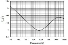
Proof of the fact that the op amp output impedance is negligible compared to a feedback resistor of 999ohm: the closed loop gain variation across the amp closed loop bandwidth (200KHz or more) is very small. The open loop output impedance usually varies significantly with frequency (see attachment), while the loop gain is constant in the closed loop bandwidth. The attached example is for OPA211.
Attachments
BTW, it should once again mention that your 20 x ADA4898 LNA has an input current noise of 10pA/rtHz (typical, low and high limits are not provided in the data sheet), which makes it usable for a source impedance of lower than 6-7ohm (otherwise the input current noise multiplied by the source impedance can no longer be ignored compared to the input voltage noise). 6-7 ohm source impedance limitation is appropriate for measuring batteries or power supplies only.
The new version there has a wet slug tantalum 4700uF / 25V there. That is much better for noise below 50 Hz but comes with a shocking price tag.
cheers,
Gerhard.
Just out of interest I checked on eBay for wet slug tantalum caps. While they are not cheap you can find some deals that may help. I found some 1500 uF/6V for $8 ea. Still lots more than an equivalent electrolytic but a fraction of the catalog price ($50 at Digikey). Some Tantalums are more like $500 ea.
BTW, it should once again mention that your 20 x ADA4898 LNA has an input current noise of 10pA/rtHz (typical, low and high limits are not provided in the data sheet), which makes it usable for a source impedance of lower than 6-7ohm (otherwise the input current noise multiplied by the source impedance can no longer be ignored compared to the input voltage noise). 6-7 ohm source impedance limitation is appropriate for measuring batteries or power supplies only.
I should mention again that 220pV/rtHz equals abt. 3 Ohms and that any source
resistance larger than that will produce more thermal noise than the amplifier.
Apart of that, 60 Ohm source resistance delivers the expected voltage noise of 1nV/rt Hz.
It's not that I hate JFETs. I just spent another rainy & stormy weekend simulating and
trying to stabilize my IF3602 amplifier. That standard architecture
"parallel FETs, optional. Cascode, op amp loop gain and feedback into the sources"
definitely has a stability problem.
I managed to stabilize the cascode itself, and even with acceptable open loop gain
the closed loop will produce neg. Rin. There are more than 2 loops.
I tried yesterday evening if other people fare better than me, and no, they don't.
SG's amplifier was too much drawing work with that over-engineered current source,
so I took something símpler, also well known here.
Lo & behold, negative input impedance @ > 500 KHz. Find a cable or inductor of the
right size and it will oscillate. Input impedance is signal generator voltage divided
by generator current, and re() is the real part of this.
And yes, I need a FET amplifier because cross correlation won't remove the noise
current effects since it's common to both parallel amplifiers if I use 2 amplifiers & cross correlation.
Attachments
Last edited:
I should mention again that 220pV/rtHz equals abt. 3 Ohms and that any source
resistance larger than that will produce more thermal noise than the amplifier.
Apart of that, 60 Ohm source resistance delivers the expected voltage noise of 1nV/rt Hz.
It's not that I hate JFETs. I just spent another rainy & stormy weekend simulating and
trying to stabilize my IF3602 amplifier. That standard architecture
"parallel FETs, optional. Cascode, op amp loop gain and feedback into the sources"
definitely has a stability problem.
I managed to stabilize the cascode itself, and even with acceptable open loop gain
the closed loop will produce neg. Rin. There are more than 2 loops.
I tried yesterday evening if other people fare better than me, and no, they don't.
SG's amplifier was too much drawing work with that over-engineered current source,
so I took something símpler, also well known here.
Lo & behold, negative input impedance @ > 500 KHz. Find a cable or inductor of the
right size and it will oscillate. Input impedance is signal generator voltage divided
by generator current, and re() is the real part of this.
And yes, I need a FET amplifier because cross correlation won't remove the noise
current effects since it's common to both parallel amplifiers if I use 2 amplifiers & cross correlation.
Never tried IF3602 and I'm not about to; I can barely justify the cost, plus that the very large parameter dispersion is to me a major turn off.
But I tried paralleling up to 64 BF862's (total of almost 1A Idss, almost 3S total transconductance) with gate inductors (1uH each) and got absolutely no stability issues. Noise was around 0.2nV/rtHz flat but the 10Hz noise performance was rather dissapointing (10...15nV/rtHz).
I will never understand how SG got 1nV/rtHz @ 10Hz with 8 x BF862, it's something that AFAIK nobody else (including myself) was able to get, without sorting the devices (which he claims he didn't). People cloning his exact design (on this forum as well) measured anywhere between 2...3nV/rtHz, which is what I got myself with another design (posted above) running @ 1.5mA/device (12 mA total). SG's design noise corner frequency is yet another mystery, I've sifted through hundreds of BF862's (purchased over time from different suppliers, from different batches) and I've never seen a noise corner frequency under 300...400Hz. The OnSemi 2SK3557 and the derived products have a slighter (5-10%) higher flat noise, but in turn a slighter low noise corner frequency (200...300Hz).
Thanks,
O.
Ovidiu, I have Groner's preamp and I did measure 0.4nV/RtHz or slightly better over most of the audio range, with the AP. Shorted input.
Jan
0.4nV/rthz flat is a no debate, easy to get. SG claims under 1nV/rthz @10Hz, which obviously yours doesn’t (if you count the drop around 10Hz). Extrapolating the curve, it appears yours is 1.5nV/rthz @10Hz, which very respectable (better than what I got, 2nV/rthz), but 50% higher than the claimed result.
At the scale of your graph the noise corner frequency is hard to evaluate, but it certainly doesn’t look under 100Hz as originally claimed. It appears to be in the hundreds of Hz, which aligns very well with mine and others results.
P.S. Also check Dmitri’s results on the low noise JFET noise corner frequencies. No known, old or new, type has under 100Hz.
Last edited:
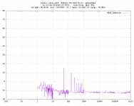
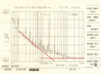
This is an example of my own (not really the best), -112dB that is 2.5nV/rtHz @10Hz, for 8xBF862. Sorry, it is not shielded.
If you look between 10Hz and 100Hz, you'll note the slope is some 13dB/decade, pretty close to the theoretical/ideal 1/f noise slope, of 10dB/decade (the balance of 3dB is usually some GR noise). And if you extrapolate at the 0.4nV/rtHz flat noise (-128dB, the lower right corner) you get a noise corner frequency anywhere between 200 and 250Hz.
I will redo this measurements as soon as I get the chance to do a decent shielding.
Attachments
I will never understand how SG got 1nV/rtHz @ 10Hz with 8 x BF862, it's something that AFAIK nobody else (including myself) was able to get, without sorting the devices (which he claims he didn't). People cloning his exact design (on this forum as well) measured anywhere between 2...3nV/rtHz, which is what I got myself with another design (posted above) running @ 1.5mA/device (12 mA total). SG's design noise corner frequency is yet another mystery, I've sifted through hundreds of BF862's (purchased over time from different suppliers, from different batches) and I've never seen a noise corner frequency under 300...400Hz. The OnSemi 2SK3557 and the derived products have a slighter (5-10%) higher flat noise, but in turn a slighter low noise corner frequency (200...300Hz).
Actually Jan, I checked again the Linear Audio Vol.3 for the SG results. In fig. 14 and the associated text he claims 0.5nV/rtHz @ 10Hz and a noise corner frequency of under 10Hz.
Which is about 3 times lower than what you got with the same design in the chart you just posted, and your noise corner frequency is over an order of magnitude higher.
This is one of those mysteries I will probably never figure out. No circuit improvement, even an "overengineered current source" can IMO justify such a low frequency performance. I would very much like to see somebody reproducing these outlandish results, yours certainly doesn't.
- Home
- Design & Build
- Equipment & Tools
- Groner's Low noise measurement amp from Linear Audio vol 3 - spare boards?