Hi all, I'm looking to build a LNA to measure power supply noise and discovered this thread after having re-read the original 2012 Linear Audio article. This looks like a great design but the specified BF862 fets are now obsolete. Any suitable substitutes?
2SK3557-6-TB-E ON Semiconductor | Mouser Canada
Thanks syn. Do the 2SK3557 fets require change any other component values / op points or deviation from the matching procedure described in the article, or are they a drop in replacement?
As far as I recall the schematic, if you get the -6 grade as indicated (Idss=10...20mA) then no further changes are required.
Much appreciated.
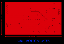
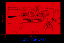
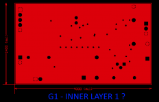
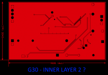
My board house is having difficulty working out the stack up from the Gerbers. The files with the extension GBL and GTL appear to be the bottom and top layers, respectively, with G1 and G30 the inner layers. But its not obvious to me (or JCL PCB) the correct ordering. Any ideas?
https://www.nanovolt.ch/publications/zip/a_low_noise_laboratory-grade_measurement_preamplifer.zip
You might have smoother sailing if you rename each of the files, following the standard filename extensions that all Chinese PCB fabs accept (in my experience anyway). It's documented lots of places but my fingertips know how to find it quickest at Seeed Studio Fusion PCB. See attachment.
Just use a free online Gerber viewer ( I like the one at www.pcbxprt.com ) to view each of the files in your Gerber zip archive. Figure out, using your vast expertise as a DIYer, that "file1.aaa" must be "layer so-and-so". Then figure out that "file2.bbb" must be "layer thus-and-such". When you've done this for all the files, rename them using the Chinese standard filename extensions. Bob's your uncle.
_
Attachments

Hi Mark
Yes, the file names in Samuel's zip file make it difficult to work out what's what. For my own designs, I use an Eagle CAM Processor I discovered on OSH Park that explicitly labels each Gerber file with a detailed descriptor; I've never had any issues with the Chinese fabs with Gerbers prepared this way.
Earlier in this thread Samuel mentioned he used Protel 95 to produce the pcb's, leading me to various online sources, including the link below, with a partial description of file extensions. Unfortunately there doesn't appear to be any standardised naming convention for inner layers.
Protel Layer and Gerber File Extension Key
I examined each of the files in GerberLogix an deduced that GBL and GTL are indeed the outer layers; hallodeletue's board photos on page one of this thread provided a reference. I'm also quite sure that G1 and G30 are the inner layers but unfortunately its not clear to me the correct ordering of these layers.
Attachments
Hi,
have somebody spare pcb for Groner's Low noise measurement amp and is willing to swap/sell?
Tnx
have somebody spare pcb for Groner's Low noise measurement amp and is willing to swap/sell?
Tnx
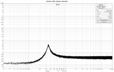
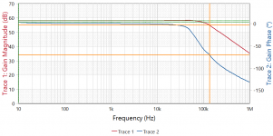
Some help needed here…. I build the Groner LNA, but I’m having trouble making it work as it is supposed to.
Above 1kHz the LNA is behaving nicely and the noise figures I read using test resistors are in very good accordance with the theoretical values and those reported in the article.
However, there is a strong and progressive reduction of the gain of the amp at frequencies below approx. 1 kHz. This reduction in gain translates into an apparently reduced noise floor at lower frequencies which is obviously no so.
Secondly, I observe a peak in the noise floor around 350 Hz which I guess is related to the 1/f noise corner of the BF862 transistors. Although this noise peak can also be seen with a 100R resistor as noise source it is apparently gone (and not just swamped) with a 1k resistor over the inputs…
I don’t know if the non-linear gain and the noise peak are related phenomena.
The LNA was build according to original BOM, but I did have to pick alternative several times due to discontinued parts. All substitutes were however (apparently) equivalent. I also build a second board and it behaves identically, so probably not just a silly stuffing mistake.
I can’t say that I obtained the BF862 from a "trusted source” so these are main suspects even if they did measure and match as described in the article. Also, at frequencies above 1kHz the LNA seems to work nicely.
Before looking for another source of BF862 and reworking the board(s) I would like to hear if anybody has a better idea of where something might be wrong.
Is it probable that non-genuine BF862s could cause the observed frequency response or I better first look elsewhere?
Has anybody else seen something similar with this LNA?
Any input would be very welcome.
Thanks,
Nic
Attachments
How do you measure that? Is this just a 1K resistor to GND from the input
and what we see is the amplifiers own noise, or is there a generator connected
through an 1K as one would really measure the gain?
The noise corner at 350 Hz could be true for the BF862, but the noise corner
has absolutely no interaction with gain. It is just the frequency below which the
transistor starts to produce more noise of its own. And that goes slowly at
10 dB/decade.
The claim of 30 Hz noise corner for the amplifier is impossible with BF862 IMHO.
That resonance that goes away with larger input resistance seems to be more a
sign of instability. The usual negative input impedance from wrong feedback is
more typical for the 70 KHz+ frequency region. Maybe there is sth. wrong with the
bias loop. For a test, you could replace the bias system with a 10 turn pot.
Also, I don't think that you have bad FETs. The BF862 is dead, but is was cheap
and has no cult state like 2SK170. Not easy to make financial gain from faking it.
And if it was bad, it would not hit just a few frequencies. Maybe not so wonderful
gain, generally more noise or lower ft, none of which would hurt here in this way.
Last edited:
gerhard is right this is probably a poor choice of time constants in the bias/low frequency cutoff part of the circuit. No money in making fake $0.25 parts.
No money in making fake $0.25 parts.
Are you joking? Here, 5% carbon resistor sold as 1% metal film resistor.
Are you joking? Here, 5% carbon resistor sold as 1% metal film resistor.
We are talking BF862.
Hi
I recently ordered a couple of PCB's of this very nice preamplifier. There are a couple of parts that are obsolete and very hard to come by. Someone already mentioned that the 2SK3557 is a valid replacement if you order the -6 variant.
Other transistors however are not mentioned, even though the BC850C and the MMBF5462. Are there any recommended replacements?
I’ve just finished complete build of this preamplifier. For the input, recommended 2SK3557-6 were used as the BF862 replacement. From batch of 20, I got two matched octets with less than 45 mV difference. That was unexpected, but it looks that those have much less Vgs spread than BF862.
MMBF5462 replacement was a challenge. I found a suitable replacement in SMP5116:
SMP5116 InterFET | Mouser Croatia
There is some discrepancy between Mouser and manufacturer data, i.e. Mouser specifying 15 V Vds breakdown voltage while this JFET has 30 V Vgs breakdown and is generally declared as 40V JFET. Anyway, I’ve made a stress test leaving preamplifier at +- 20 V supply for hours and everything was fine.
Attachments

Noise floor? Freq. response in audio range?
Scope porn very welcome 😀
My build(s) are still out of use because of non-linear frequency response below 1 kHz😕
Scope porn very welcome 😀
My build(s) are still out of use because of non-linear frequency response below 1 kHz😕
Consider those pictures as the foreplay. 🙂
Output level, with shorted input, is to low for the oscilloscope which displays only environment noise.
I have a desktop multimeter with 10 uV resolution and 1 Hz to 100 kHz RMS bandwidth, but measuring AC at mV levels is a challenge, due environment noise, and it can never display that low in the AC mode: Review of East Tester ET3240
Adding various resistors at the input, changes output voltage value by calculated noise difference x 1000, so it looks to work OK.
I need to purchase Focusrite for the better noise and response measurements.
Last edited:
Noise floor? Freq. response in audio range?
Scope porn very welcome 😀
My build(s) are still out of use because of non-linear frequency response below 1 kHz😕
Looks good to me:
Attachments
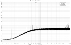
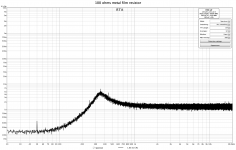
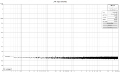
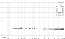
I visited today local “Music shop” and returned home with nice scarlet colored device: Focusrite solo. Granted, I barely have a clue how to measure properly with REW software and no proper calibration was done, but here are the first results. I’ve measured with same settings as NicMac, so results can be compared.
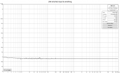
Resulting noise spectrum is exactly like in the original article: almost linear in the whole bandwidth and with, what looks like, noise corner at 10 Hz. This is better visible on smoothed measurement.
Resulting noise spectrum is exactly like in the original article: almost linear in the whole bandwidth and with, what looks like, noise corner at 10 Hz. This is better visible on smoothed measurement.
Attachments
3 "sanity checks" place resistors of 60R, 390R and 10kR on the input of the amplifier -- you should be able to see their thermal noise of 1, 2.5 and 12.7nV/Rt Hz on the FFT -- if not you have to compensate the FFT for bin size and windowing methodology.
If you can download the data into Excel, you can make the adjustments to get to these figures. It's explained in an Audio Precision white paper: "FFT Scaling for Noise" FFT Scaling for Noise - Audio Precision -- if you can't download I'll send you a PDF
If you can download the data into Excel, you can make the adjustments to get to these figures. It's explained in an Audio Precision white paper: "FFT Scaling for Noise" FFT Scaling for Noise - Audio Precision -- if you can't download I'll send you a PDF
Last edited:
- Home
- Design & Build
- Equipment & Tools
- Groner's Low noise measurement amp from Linear Audio vol 3 - spare boards?