I also found my best result, 2nV/rtHz @10Hz, the noise corner frequency is about the same, between 200 and 250Hz. This one has lower noise @10Hz simply because, by pure chance, the 8xBF862 have close to ideal 1/f noise, dropping at 10dB/decade.
And also attached is fig. 14 of SG article in LA, his voltage noise results and comments. I hope this is considered fair use, otherwise some moderator can remove the attachment.
And also attached is fig. 14 of SG article in LA, his voltage noise results and comments. I hope this is considered fair use, otherwise some moderator can remove the attachment.
Attachments
NXP claimed 800 pV/rtHz at 100 KHz and Idss.
I found Idss to be 12.x mA when I measured abt. 150 pcs. ; reducing this to 1 mA
per transistor would decrease gm by sqrt 12 and noise performance by sqrt sqrt 12
= 1.86. So, typical voltage noise would be 0.8nV * 1.86 = 1.49 nV/rt Hz for 1 transistor,
at 100 KHz. With 8 transistors, we would end at 527 pV/rtHz, still respectable.
Then there is the 1 Ohm source resistor that adds geometrically 129 pV/rt Hz.
Really low current density is said to be good for 1/f behavior but the corner
frequencies claimed here are a far cry from the corners seen at product delivered
from Digikey and Mouser.
Someone with an existing amplifier should verify the gain at the
lower corner; maybe the bias servo does creative things. It happens.
See my yesterday simulation above.
If we find out new things, we should move that to the "Scott's take..." thread;
it's the epicentrum of insanely low noise amplifiers here and it would be nice
to have the interesting stuff in one place.
NXP claimed 800 pV/rtHz at 100 KHz and Idss.
I found Idss to be 12.x mA when I measured abt. 150 pcs. ; reducing this to 1 mA
per transistor would decrease gm by sqrt 12 and noise performance by sqrt sqrt 12
= 1.86. So, typical voltage noise would be 0.8nV * 1.86 = 1.49 nV/rt Hz for 1 transistor,
at 100 KHz. With 8 transistors, we would end at 527 pV/rtHz, still respectable.
Then there is the 1 Ohm source resistor that adds geometrically 129 pV/rt Hz.
Really low current density is said to be good for 1/f behavior but the corner
frequencies claimed here are a far cry from the corners seen at product delivered
from Digikey and Mouser.
Someone with an existing amplifier should verify the gain at the
lower corner; maybe the bias servo does creative things. It happens.
See my yesterday simulation above.
If we find out new things, we should move that to the "Scott's take..." thread;
it's the epicentrum of insanely low noise amplifiers here and it would be nice
to have the interesting stuff in one place.
Well, yes, lowering current lowers the 1/f noise and increases the flat noise. I did both @1.5mA (the results posted above) and close to Idss, and the noise changes with much less than the current ratios at the 1/4 power. I was myself a strong believer in the 1/4 law for noise to current dependency, but found experimentally the exponent is more like 1/7...9. I cannot explain this on stationary device physics only, I'm pretty confident it is largely a thermal effect.
The 1/f noise increases significantly with the drain current; at Idss=15mA noise @10Hz is about 8-10nV/rtHz, so a x5 increase over the Id=1.5mA case above.
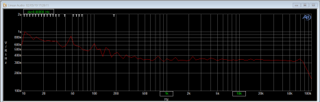
Thought myself about some LF gain issues, and Jan's results seem to suggest something like this (see the noise drop around 10Hz).
Last edited:
Just out of interest I checked on eBay for wet slug tantalum caps. While they are not cheap you can find some deals that may help. I found some 1500 uF/6V for $8 ea. Still lots more than an equivalent electrolytic but a fraction of the catalog price ($50 at Digikey). Some Tantalums are more like $500 ea.
Yes, but the reason for the tantalums was the very low leakage current.
I don't know if they keep it up in their 2nd life.
BTW, I found no drawback with good quality Al electrolytics; try them first
by all means.
The tantalums feel really heavy. If you lift an Al-lytic after them, they
seem to be empty.
Also, my AVX tantalums still have 400 mOhm series resistance according to the
data sheet. Kinda disappointing at this price.
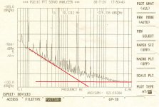
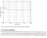
I also found my best result, 2nV/rtHz @10Hz, the noise corner frequency is about the same, between 200 and 250Hz. This one has lower noise @10Hz simply because, by pure chance, the 8xBF862 have close to ideal 1/f noise, dropping at 10dB/decade.
And also attached is fig. 14 of SG article in LA, his voltage noise results and comments. I hope this is considered fair use, otherwise some moderator can remove the attachment.
Fair use is OK with me. I blew up that curve I posted before, and indeed there seems to be a difference. To be fair, I should run a baseline for the AP itself as well of course.
Jan
Attachments
I just checked the two I got from eBay. . . 1500uF@6V The capacitance checks out and the ESR is 400milliOhm at 100Hz dropping to 200 milliOhm at 100KHz. I I would need to do a cal for those to verify the ESR if its really important. I'm not sure how to check the leakage at 6V. My 4329's lowest voltage is 10V. I suspect the leakage would be less than I can reliably measure with a relatively normal DVM.
400 mOhm is abt 80 pV thermal noise. It adds up!
The obvious rule, any added uncorrelated noise source can be safely ignored if it's equivalent noise resistance is less than 1/3 out of other noise source(s) equivalent noise resistance. Case in point, if the amp has 250pV/rtHz, 400mOhm can be safely ignored, the contribution to the noise budget will be only 11%, to 270pV/rtHz.
Me, i"m having problems accepting measurements claiming to be accurate to the second decimal after nV/rtHz. You can mention it, but when I read 0.25nV/rtHz and 0.27nV/rtHz to me is about the same thing.
You can mention it, but when I read 0.25nV/rtHz and 0.27nV/rtHz to me is about the same thing.
Statistically, yupp. All about 1/SQRT 2
Me, i"m having problems accepting measurements claiming to be accurate to the second decimal after nV/rtHz. You can mention it, but when I read 0.25nV/rtHz and 0.27nV/rtHz to me is about the same thing.
If you mean me, I have measured 200 pV/rt Hz for the 20x ADA4898 and derated
it to 220 for publication. I'm used to derating from my daytime job in space payloads.
But then , 400 mOhm / 80 pV is a definitely taking a hit when the step from 400 pV
to 200 pV /rtHz was quadrupling the bill of material. And the AVX 4700U/25V wet slug
did cost €120 or so at Digikey. Vishay would have been more than twice that.
With organic polymer alu I could have shaved off a few op amps and their noise current with the same result.
Panasonic SEPF proved to be no drawback as I found out in the 70 pV amplifier from
AOE III. But to be able to say that the Panasonics are no drawback, I first must have
the wet slugs in NEW state to compare with.
Comparing to 30 year old NOS from ebay does not count.
And Jim Williams of LT had a different position, so it's better not to take that lightly.
cheers, Gerhard
Last edited:
If you mean me, I have measured 200 pV/rt Hz for the 20x ADA4898 and derated
it to 220 for publication. I'm used to derating from my daytime job in space payloads.
But then , 400 mOhm / 80 pV is a definitely taking a hit when the step from 400 pV
to 200 pV /rtHz was quadrupling the bill of material. And the AVX 4700U/25V wet slug
did cost €120 or so at Digikey. Vishay would have been more than twice that.
With organic polymer alu I could have shaved off a few op amps and their noise current with the same result.
Panasonic SEPF proved to be no drawback as I found out in the 70 pV amplifier from
AOE III. But to be able to say that the Panasonics are no drawback, I first must have
the wet slugs in NEW state to compare with.
Comparing to 30 year old NOS from ebay does not count.
And Jim Williams of LT had a different position, so it's better not to take that lightly.
cheers, Gerhard
Told you I have little interest in massive bipolar paralleling, be it transistors or opamps. What input impedance can you count on this 20 x ADA? Any added resistor in parallel with the inputs will add to the input current noise, so not only are you restricted to very low source impedances, but also to very low input impedances, which in turn may load the DUT batteries with high currents. IMO a mess to manage.
My JFET input LNA uses a film 1uF in 1206, wtf, why would I invest in a $150 wet slug?
I’ll show you when I’m done a 64 x BF862 LNA. Preliminary measurements are showing it’s also around 0.25nV/rthz.
About 10K.
Plus 10K, unlike your HPS 5.1 in the simulation 10 posts above, that turns to a negative
real part above 500 KHz. And I can see these negative impedances on the vector network
analyzer on similar amplifiers. They are real. And that you see the oscillations only
with the "right" input termination does not make it better.
Or that you don't hear the birdies after your audio amplifier because it's 1 MHz.
The 20 ADA4898 are unconditionally stable. Harmless, predictable, the right thing to measure
noise on supplies, LEDs, Regulators, voltage references, oscillator leveling loops, oscillator
phase noise after ring mixers and so on.
With FET amplifiers, I'm down to 160 pV/rtHz. And with a true 30 Hz 1/f noise corner
and just 2 TO-5.
And in the section "plowing with the power of a 1000 chicken": I have 32 BF862 and their
ON Semi successors already behind me, individually cascoded with MMBFJ310 or so.
Not very attractive.
Attachments
Last edited:
About 10K.
Plus 10K, unlike your HPS 5.1 in the simulation 10 posts above, that turns to a negative
real part above 500 KHz. And I can see these negative impedances on the vector network
analyzer on similar amplifiers. They are real. And that you see the oscillations only
with the "right" input termination does not make it better.
Or that you don't hear the birdies after your audio amplifier because it's 1 MHz.
The 20 ADA4898 are unconditionally stable. Harmless, predictable, the right thing to measure
noise on supplies, LEDs, Regulators, voltage references, oscillator leveling loops and so on.
With FET amplifiers, I'm down to 160 pV/rtHz. And with a true 30 Hz 1/f noise corner
and just 2 TO-5.
And in the section "plowing with the power of a 1000 chicken": I have 32 BF862 and their
ON Semi successors already behind me, individually cascoded with MMBFJ310 or so.
Not very attractive.
Well, you seem to be in the “money no objection” camp, since you can afford spending $150 or more on wet slugs, interfet devices to sort from, or opamps to parallel.
About the negative impedance, it exists, but I never had any problems managing it with the proper gate inductors; choosing the proper inductors (Q) and placement is though critical.
And set aside the input current noise, 20 x ADA4898 will have, according to the data sheet, a worst case input bias current of about -8uA, and best case -2uA, which will give you 20...80 mV input offset (and with the associated drift) with 10k, which at a gain of 60dB may in principle bump the output into the rails. You may get lucky with the statistical distribution, balancing the input +/- currents, but I won’t put my job on the line for the next board results.
For the rest, it’s in the eye of the beholder. Paralleling 20 x ADA4898 op amps looks to me like a desperate, heroic, expensive, power hungry (~5W or so at +/-15V), “just because I can” solution to a non existing problem but hey, that’s just me.
P.S. There are no simulations by me 10 posts above, only some measurements.
Last edited:
> Well, you seem to be in the “money no objection” camp, since you can afford
> spending $150 or more on wet slugs, interfet devices to sort from, or opamps to parallel.
So what. One IF3601 for €18 delivers 300 pVrtHz with 30 Hz 1/f corner. Not at 5 mA
as promised, but at 12 mA. That's not far from the 250 pV you claim for your 64
BF862. I can see no financial advantage for the BF862 herd. Probably there is
even room for a IF3602 dual which would take the lead noise-wise.
WRT 1/f, there is no competition at all.
And, for the wet slug tantalums: I do not buy them day for day. But I need a minimum
amount of them for characterizing. I made it clear enough that I would prefer
Panasonic organic grown alu. I'm a free lance mixed signal developer and my
customers assume properly that I do not base design decisions on hearsay.
In precision timing, noise and temperature are your foes.
> About the negative impedance, it exists, but I never had any problems managing it
> with the proper gate inductors; choosing the proper inductors (Q) and placement is
> though critical.
Gate inductors are just what is needed to make it oscillate. The input impedance
looks like a capacitor in series with a negative resistor. Add an inductor and you
have a resonant circuit with negative damping.
The hope is that the inductor pushes the resonance so high that the transistor runs out
of steam, or in the case of ferrite beads, that their losses are so large that they cancel
the negative impedance. That does not happen. A bead that has 100 Ohms at 100 MHz
has next to nothing at 1 MHz. There, it has quite good a Q.
And if it had significant losses at AF, it would also produce the equivalent noise.
One cannot fool mother Nature.
> And set aside the input current noise, 20 x ADA4898 will have, according to the data
> sheet, a worst case input bias current of about -8uA, and best case -2uA, which
> will give you 20...80 mV input offset (and with the associated drift) with 10k,
> which at a gain of 60dB may in principle bump the output into the rails.
> You may get lucky with the statistical distribution, balancing the input +/- currents,
> but I won’t put my job on the line for the next board results.
10 KOhm as a bias resistor in front of the 20 op amps produces -1.5V offset at the 20
outputs. There is no statistic involved. No bias current canceling and no rail-2-rail-input tricks.
And if it was 5 times more, I would reduce the bias resistor to 2K.
> For the rest, it’s in the eye of the beholder. Paralleling 20 x ADA4898 op amps looks
> to me like a desperate, heroic, expensive, power hungry (~5W or so at +/-15V),
> “just because I can” solution to a non existing problem but hey, that’s just me.
It runs here from 2 * 5 AA NiMH cells that usually last for a working day.
Nothing like 5W or +-15V. That's not a HPS5.1 that runs on +-18V, to make the
headroom crowd happy (precisely on the abs.max. ratings for the LMH6321, btw)
It does not run at 1A Idss like the 64 BF862.
> P.S. There are no simulations by me 10 posts above, only some measurements.
I was so free to provide the simulation in post 325. LTspice file is available if wanted.
Last edited:
Gate inductors are just what is needed to make it oscillate. The input impedance
looks like a capacitor in series with a negative resistor. Add an inductor and you
have a resonant circuit with negative damping.
The hope is that the inductor pushes the resonance so high that the transistor runs out
of steam, or in the case of ferrite beads, that their losses are so large that they cancel
the negative impedance. That does not happen. A bead that has 100 Ohms at 100 MHz
has next to nothing at 1 MHz. There, it has quite good a Q.
The gate inductors do NOT have to be hi Q, they have to be amortized by a small series resistance (low hundreds of mOhm). I'll let you find the optimum to avoid oscillation, while I wonder why IF3601 should have lesser of the same problem. Negative input impedance is coming from the intrinsic device, I could explain exactly the mechanism, but since you are not interested in FETs...
And paralleling IF3601 is a hard thing to do, given the large parameters (Vp) dispersion. Matching devices makes such an attempt very expensive. BTW, I got the 2SK3557 from Arrow for 18 cents a pop, that is 0.15 Euros which rounds for 10 euros for 64 devices. About a quarter the price of two IF3601's, assuming you are lucky enough to get them more or less matched.
Enough of this...
I said nowhere they had to be hi Q, I said that they are high Q at low frequencies, and
I was talking about ferrite beads. That can easily be checked on the impedance bridge,
does not even need the VNA.
I also said that _IF_ they had a dissipative loss at low frequencies to counteract
the negative input impedance, they would generate thermal noise just like a resistor
of the same effect. Then I can use a resistor just as well.
Two matched IF3601 are one IF3602. Now, that was a hard thing to do. And the real
cost for me is not a somewhat overpriced twin transistor, it is unpaid manpower.
And it takes a lot of manpower. But always a better deal than one meter of high end
speaker cable.
I assume you have seen my matching tests at
< 8pcs_IF3602 | 8 pairs of Interfet IF3602 JFETs Id vs Vgs | Gerhard Hoffmann | Flickr >
The idea that I "have no interest in FETs" comes as a slight surprise. I have
communicated enough designs. I just don't publish them as perfect.
But negative input impedance is a drawback that must not be hidden.
And thank you, but the mechanism in the FET is described both by Staric
(with a small v above the c) and Hollister in their respective wideband
amplifier books, both from Tektronix, back then when Tek still was Tek
and Keysight still was HP.
I'll leave the last word to you.
Gerhard
I'm thinking of building this measurement amplifier having seen the reference to it in Self's Small Signal Audio Design.
I note that Samuel has kindly made gerber files available on his website but I was wondering if anyone had already ordered some boards and had any spare.
Thanks
Steve
Hello, you can purchase your linear power schematic and BOM
- Home
- Design & Build
- Equipment & Tools
- Groner's Low noise measurement amp from Linear Audio vol 3 - spare boards?