Guy who designed signal generator(i posted PCB on previous page) used C&K switches, i just said lorlin cause they both got same footprint and coudn't remember C&K name.
About other ways to to make switching i would prefer relays,if we go with mosfets things get complicated and prices rises up. I used some cheap chinese reed relays before and they work nice and their footprint is identical to some brand name relays,atm i don't have access to my datasheet base so i don't know brand name relays models.
But if we choose relays for this i would suggest daughterboad with relays would be good idea. Placing relays on main board would result in pretty large board. If i'm not wrong 49 relays is needed and that takes a lot of space.
I just bought an "Applied Physics 428C DC Clip-on Milliammeter" off of Epray. I somehow don't expect it to work, but if it does, it will need a probe and calibration.
I noticed that it's ranges are bounded by 10mA FS and 2A FS. For this project here, I would beg that you keep the original ranges that the real 428B has.
-Chris
I noticed that it's ranges are bounded by 10mA FS and 2A FS. For this project here, I would beg that you keep the original ranges that the real 428B has.
-Chris
I believe they still make that instrument. Its been revised https://www.appliedphysics.com/_main_site/wp-content/uploads/Model-428D-Clip-On-Milliammeter.pdf mostly it seems in ranges.
@Anatech
I'll make PCB with extended ranges. If you wanna keep original ranges you will need to contact Elvee and see what he's gonna say. My guess that changing resistor values for range selection should do the trick but maybe you will need to tweak a bit value of compensation parts.
I'll make PCB with extended ranges. If you wanna keep original ranges you will need to contact Elvee and see what he's gonna say. My guess that changing resistor values for range selection should do the trick but maybe you will need to tweak a bit value of compensation parts.
Hi Demian,
The one I saw was the 428D. It has the same restricted ranges as the 428C I bought (thanks for the links!). I got it just to make do between the time the boards are ready and now. I had a spare probe, so this will put it in service. I'm not really sure about how it will perform, but at least I still have my 428B I can pull out to use.
Hi Davor,
I'll ask Elvee about the ranges. It's the same probe as the 428B, so it isn't a case where the probe can't do it. I would accept reduced accuracy on the 10A range as well. Ultimately, I would like two boards / kits to take over for the pair of 428B's I am using.
For those of us who have never used a current clamp meter for DC measurements, once you have tried it once, you'll understand and end up using it a lot more. The probes they make for oscilloscopes are too expensive for us as a rule. That and most oscilloscopes aren't that accurate unless you have new / current model where the accuracy has been enhanced. That would be an expensive 'scope.
-Chris
The one I saw was the 428D. It has the same restricted ranges as the 428C I bought (thanks for the links!). I got it just to make do between the time the boards are ready and now. I had a spare probe, so this will put it in service. I'm not really sure about how it will perform, but at least I still have my 428B I can pull out to use.
Hi Davor,
I wish I could read your language on that forum. The use of C0G ceramic capacitors is fine as they work about the same as polypropylene capacitors. Thank you re: the normal ranges the 428B has.This is forum where i'll design PCB
I'll ask Elvee about the ranges. It's the same probe as the 428B, so it isn't a case where the probe can't do it. I would accept reduced accuracy on the 10A range as well. Ultimately, I would like two boards / kits to take over for the pair of 428B's I am using.
For those of us who have never used a current clamp meter for DC measurements, once you have tried it once, you'll understand and end up using it a lot more. The probes they make for oscilloscopes are too expensive for us as a rule. That and most oscilloscopes aren't that accurate unless you have new / current model where the accuracy has been enhanced. That would be an expensive 'scope.
-Chris
Nothing helpful is said in that topic on forum i guess most of people don't consider this device to be usefull and don't have any probes.Some people say that this device is outdated and would be better to get some other probe that has bigger BW. I'm mostly working on audio circuits and not designing or repairing complicated SMPS's so this probe is more then enough for me. I was looking for some Tektronix clip-on probe that prices for those are a bit too much for me.
You can use google translate or some addon for web browser to translate text on that forum. Language is serbian and croatian.
I have made some progress with routing PCB, degausser will be on main PCB,there will be daughterboard that will have relays or rotary switches depending your preferences.
You can use google translate or some addon for web browser to translate text on that forum. Language is serbian and croatian.
I have made some progress with routing PCB, degausser will be on main PCB,there will be daughterboard that will have relays or rotary switches depending your preferences.
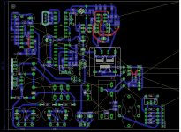
I have made some progress in routing PCB. I didn't put any ground plane or put some effort in routing ground traces i'm atm just fiddling with components layout. All components that require tweaking(according to Elvee alignment guide) are tht including resistors for range selection i think it's easier to measure and change tht component then smd.
So far i have placed components for degausser, clock generator,group of those 5 transistors and first "switch" for range selection, but i think i'll have to make some serious rearrangement cause trace that leads from pin 8 of CD4069 to CN4053 is gonna be really long. I knew this is gonna be long process when i decided to design PCB so i'm not rushing.
So far i have placed components for degausser, clock generator,group of those 5 transistors and first "switch" for range selection, but i think i'll have to make some serious rearrangement cause trace that leads from pin 8 of CD4069 to CN4053 is gonna be really long. I knew this is gonna be long process when i decided to design PCB so i'm not rushing.
Attachments
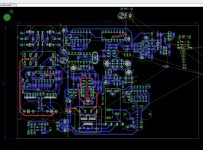
A bit more progress in routing PCB.
Now i have come to part where decision what kind of relays for switching ranges and type of measurement we gonna use. I need to make daughterboard that will fit mainboard so i need to know what relay we gonna use. Ofc there will be option with rotary switch daughterboard but since there are non 3P6T PCB mount rotary switch i will need to work out a bit more before i come up with some solution.
So relay option.If i counted correctly we need 19 of them. I was thinking about reed relays in SIL package cause they are small and you can put them a lot on small area. Example of them is in link below.
https://hr.mouser.com/datasheet/2/240/Littelfuse_Reed_Relays_HE3600_Datasheet.pdf-876890.pdf
Attachments
Hi Khadgar2007 ,
I would highly recommend we go with relays in the DIL package, "2 form C" types that are common. You can get these in a sealed version that will last, and is easy to find replacements for. I'm not sure what you are switching, but for control signals you might consider using CMOS analogue switches like the 4066B. These would only be for logic switching, not the actual signal itself.
If they have enough contact positions, a four pole rotary switch could be used instead of a three pole switch. Again, easier to find replacements for and suppliers.
19 relays seems like quite a lot. You would also have to figure out the maximum number of relays that would be energized at any one time and use that figure to design you power supply. My biggest fear on the relay selection is that the contacts might not be the best with reed relays. Long term reliability hasn't been great with these and most test equipment would use the DPDT types in a DIL package. I'm thinking of signal relays here (< 2A) as I don't see you switching the actual measured quantity.
At least the relays you linked to are cheap if we really need that many relays.
-Chris
Number of relays you can check in Elvee schematic. Switches in schematic are marked S1 A/B/C and one that is not marked that that one switches what type of measurement you take(AC,ACrms,DC,...)
Signal/current that is measured is switched with this relays/rotary switches etc.
Decision for choosing SIL reed relay or DIL DPDT. I was thinking about SIL reed cause they are cheap, a bit thinner then DIL. I heard both story about reed relays, but can't think some solid reason why some people say they are good and some that they are bad. I guess its cause contacts in reed relay needs to be magnetic so maybe material doesn't have good mechanical characteristics.
Method for control switching relays on/off i'll leave to individual. I plan to use normal rotary switch mounted on front panel and switch control voltage for relays with it. Simple as possible. I can make room for some CMOS switch so if somebody plans to use those he doesn't have to add extra board.
Amount of relays that would be turned on would be 5 in worst case scenario.
I don't plan to design PSU. There are lots of designs all around internet. And Elvee used simple 7812/7912 PSU that can anybody make at home. I plan to use he's no-noiser schematic but i still haven't design PCB.
Hi Khadgar2007,
In my experience, reed relays fail more often that the gas filled replays that are DPDT. However, we'll see how these do. I would control them with a switch.
I was only wondering if some of the signals could be controlled with an analogue switch instead of a relay, that's all.
-Chris
In my experience, reed relays fail more often that the gas filled replays that are DPDT. However, we'll see how these do. I would control them with a switch.
I was only wondering if some of the signals could be controlled with an analogue switch instead of a relay, that's all.
-Chris
Like i said it's up to people who will build this thingy to choose way of switching signals. I said earlier that best thing would be PCB mounted rotary switch but since S1 is 3P6T i couldn't find them for PCB mounting so daughterboard will be needed.
Main PCB is gonna be mandatory, rest of project is free for all thingy. So people can choose their way for switching signals,PSU unit and so on.
But, there is a way around i think... If you look at schematic 200uA and 2mA range is cause of all this switching problem. I know it's not user friendly but i could put that S1 is 2P6T and place extra toggle switch for 200uA range. So when you are on 200uA range S1A is on 200uA, S1C is shorted. When you switch with S1A to 2mA you need to manually switch off S1C. That way i could use normal rotary switch and signal paths would be as short as they can be.
If that is the challenge is the circuit really sensitive to the wiring? There are 3P 6T switches on eBay for around $10. Its 24 wires but its not insurmountable. I would probably package the system with the switch below the PCB so the wires aren't in between parts. Its probably the most straightforward solution.


"Really soon" became almost delay for over a year. Sreaves contacted me couple of weeks ago asking did i made some progress with PCB and made some suggestions. That gave me some motivation to start again with this.
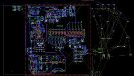
Sreaves suggested that i go back to reed relays switching,which i did and said he's gonna make trueRMS converter. Plan is to put everything required for this project on same board(PSU,trueRMS converter,main board,"preamp board") and you snap off those boards from main one and place them where you want them to be depending what enclosure you have. There will be place on main board where you plug in "preamp board"(preamp is part of schematic that contains Q7,8,9 and designated parts around them). That board is gonna be small and should be easy to shield it like Elvee suggested.It's up to individual how they gonna shield it.
I have done most of the layout and what is left is mostly power supply lines for OPamps. Some grounds will go to ground plane and some have individual trace to ground center point.
Attachments
- Home
- Design & Build
- Equipment & Tools
- Modernized HP428 clone