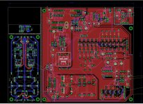
A bit more progress with layout. You can see main circuit board and other ones that you can snap off from it,such as power supply, preamp. I'm still not sure what i'll do with zero adjustment part which is now above PSU, shall i add it to PSU board or make a mini-PCB that you attach to potentiometer.
TrueRMS circuit is gonna wait a bit cause Sreaves is quite busy atm. I'm hoping it's not gonna be big so it can fit in upper-left part of PCB.
Until then i'll need to check track width,make design rule check, fix silkscreen so it doesn't overlaps and you can read it without problem and lots of that small details that i usually don't do cause 95% PCBs i make are single sided and i make them at home. So no silkscreen,no soldermask,etc... 😀
Attachments
> shall i add it to PSU board or make a mini-PCB that you attach to potentiometer.
Probably better to avoid the multiplication of PCB's: if it can be merged with something else, it is the way to go
Probably better to avoid the multiplication of PCB's: if it can be merged with something else, it is the way to go
I placed zero adjustment on PSU board and i got sorted silk-screen.
Btw i found in Mouser potentiometer with "double shaft" for this application 652-PTH902135F503B4
Btw i found in Mouser potentiometer with "double shaft" for this application 652-PTH902135F503B4
For those still interested, I have decided to disclose the contents of the mystery, blanked out box of the schematic (the RMS to DC converter):
https://www.diyaudio.com/community/...here-is-the-legacy-thread.387391/post-7055304
https://www.diyaudio.com/community/...here-is-the-legacy-thread.387391/post-7055304
Elvee, what will i do with you? 😀
Couldn't you announce this like month ago? Last year i had chat with Sreaves about RMS converter and he suggested one that is no longer available(due to shortage of semiconductors) so i bought two others just month ago to play with them and implement them and now you come up with this.
Maybe you saw but i added reed relays instead of rotary switches so i got away with only 4 relays when it comes to selecting what type of voltage value will be shown on display/meter. And now you come with tested circuit(which is good) but like somebody said long time ago, i will need a bigger boat...i mean PCB if i go that way.
It is tempting and i already got some kind of idea how to make it work. I planed to have small daughterboard attached to main one for RMS converter but i could make it bigger so it can fit all 10 relays that are needed to switch voltage you measure and rest of electronic. Advantage is that you can get most of parts easily even with semiconductor shortage, LT1056 is unavailable in mouser but i bet you can replace it with some other opamp.
Sorry about the inconvenience and the unfortunate timing, but after 8 years (much more in fact, because the rms/DC was developed years earlier), I saw no point in withholding it any longer, which is why it appeared just now...
My advice would be to stay with your current configuration: AD636 and the like work well, and my unusual converter will not bring significant improvement, but it is not immune, in theory, to aliasing effects.
It doesn't seem to be a problem in practice, but if your test frequency happens to be exactly 400Hz, you might notice it.
It doesn't seem to be a problem in practice, but if your test frequency happens to be exactly 400Hz, you might notice it.
Was just joking. 🙂
Sreaves suggested AD8436 but it's unobtainium atm, so i bought AD737 and AD637. I didn't consider AD636 cause price is a bit hot.
I have lots of other work to do so "development" od RMS converter is a bit postponed. It's not like it will be big development cause it's chip and most stuff is in datasheet but i will have to proper test it before publishing it.
Note that in the actual build, the 2K2 R6 is formed by a 2K0 fixed resistor and a 470 ohm trimmer adjusted during the calibration to read the exact rms value of a reference sinewave
Another important practical consideration: for a good accuracy and linearity, it is essential that the 220n capacitor has good properties, low DA, low losses, etc. Thus in practice a PS or PP capacitor.
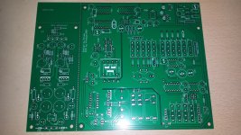
Hello people. It's been quite a while since i finished layout but i didn't ordered PCB until now cause i was hoping i'm gonna design trueRMS converter in shorter time and added it to main pcb layout. Sadly that didn't happen so i ordered pcb's without that part. PCB for converter should be simple so i will diy it at home when i get to that point.
I got couple of jobs that pays bills that need to be done so not sure when i'm gonna start this interesting project. Maybe i'll start soldering bits and pieces together when i get some free time.
I got couple of jobs that pays bills that need to be done so not sure when i'm gonna start this interesting project. Maybe i'll start soldering bits and pieces together when i get some free time.
Attachments
Clean looking boards.
If you're selling them, please let me know, or can I get the files to have one made?
I know what you're saying. Things were slow, then life simply got very busy. Especially lately!
-Chris
If you're selling them, please let me know, or can I get the files to have one made?
I know what you're saying. Things were slow, then life simply got very busy. Especially lately!
-Chris
I would consider selling them but first i would like to built one and see if pcb works as it should,you know routing gods can be very mischievous and this was not simple project so i would like to be first one to test layout.
And since Elvee was so nice to share it for free i will share entire documentation eagle,gerber files once i have tested it. But since i will have extra three pcb's i would like to sell them so they don't collect dust somewhere in corner.
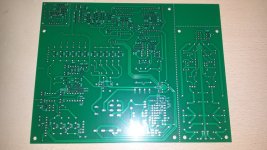
Btw last time i checked jlcpcb charged some big extra money for v-groove cuts so i made lots of holes for snapping little boards of main one. In theory that was ok idea but in practice i will need to use some tool to cut them off. These chinese fr4 boards are really solid build.😒
edit: I just did two cuts with sharp knife over holes on boths sides of board and it snapped like nothing so i guess idea wasn't that bad.
And since Elvee was so nice to share it for free i will share entire documentation eagle,gerber files once i have tested it. But since i will have extra three pcb's i would like to sell them so they don't collect dust somewhere in corner.
Btw last time i checked jlcpcb charged some big extra money for v-groove cuts so i made lots of holes for snapping little boards of main one. In theory that was ok idea but in practice i will need to use some tool to cut them off. These chinese fr4 boards are really solid build.😒
edit: I just did two cuts with sharp knife over holes on boths sides of board and it snapped like nothing so i guess idea wasn't that bad.
Last edited:
That works for me, and thanks.
I use a Chinese outfit. Much less expensive, high quality and delivery about a week. North American board houses are stupid expensive, and I have used them. The quality is absolutely no better.
I use a Chinese outfit. Much less expensive, high quality and delivery about a week. North American board houses are stupid expensive, and I have used them. The quality is absolutely no better.
A progress, or actually one step forward,two steps back. 🤣
PSU was assembled and i was trying to test it when things went south.Lesson learned, when Elvee says put general type of caps in d-noizer then put them,not Panasonic FR ones... I have one d-noizer that is working and it's in my low thd signal generator so i compared those two. I have found that i put Panasonic FC caps in one that is working, i guess i'll buy some FC series caps for this cases where i don't need low esr.
Here is PSU that worked like charm from moment i soldered last component. Actually i have one FR series cap and it's in feedback line from PSU output.

Here is one that didn't worked like charm, took me half morning to figure out what the heck was going on...

EDIT: Btw i have loads of polymer hybrid caps(Panasonic ZA) in that signal generator as decoupling for all IC's and it seems d-noizer works like a charm as long you have some longer wire and resistance between those two.
PSU was assembled and i was trying to test it when things went south.Lesson learned, when Elvee says put general type of caps in d-noizer then put them,not Panasonic FR ones... I have one d-noizer that is working and it's in my low thd signal generator so i compared those two. I have found that i put Panasonic FC caps in one that is working, i guess i'll buy some FC series caps for this cases where i don't need low esr.
Here is PSU that worked like charm from moment i soldered last component. Actually i have one FR series cap and it's in feedback line from PSU output.
Here is one that didn't worked like charm, took me half morning to figure out what the heck was going on...
EDIT: Btw i have loads of polymer hybrid caps(Panasonic ZA) in that signal generator as decoupling for all IC's and it seems d-noizer works like a charm as long you have some longer wire and resistance between those two.
Last edited:
- Home
- Design & Build
- Equipment & Tools
- Modernized HP428 clone