It is important also. However, in solid state deisgns with very wide bandwidth the phase changes at audio freqs are small and relegated to secondary status. More important would be group delay measurements which i have been interested in for decades. But again, with near DC response with digital and SS that isnt an issue.... but with speakers, filters, cross-overs and many tube circuits it is still useful to measure and find ways to reduce or compensate.
We are primarily focused here on the test equipment itself rather than a lot of its' applications.
THx-RNMarsh
We are primarily focused here on the test equipment itself rather than a lot of its' applications.
THx-RNMarsh
It is important but I haven't found any FFT software that displays phase. Equipment for measuring phase is very expensive.
You can't really derive phase without a differential measurement. Several of the speaker programs can do it. The best is Praxis for that since Praxis is modeled on a Vector Network Analyzer.
Real network analyzers are expensive.
I'm told that the next gen QA audio box may be able to display phase, but you need to remove the delay for that to mean anything. It all gets pretty involved.
Sent from my XPS 12-9Q33 using Tapatalk
Real network analyzers are expensive.
I'm told that the next gen QA audio box may be able to display phase, but you need to remove the delay for that to mean anything. It all gets pretty involved.
Sent from my XPS 12-9Q33 using Tapatalk
You can't really derive phase without a differential measurement. Several of the speaker programs can do it. The best is Praxis for that since Praxis is modeled on a Vector Network Analyzer.
Real network analyzers are expensive.
I'm told that the next gen QA audio box may be able to display phase, but you need to remove the delay for that to mean anything. It all gets pretty involved.
Sent from my XPS 12-9Q33 using Tapatalk
Have you looked at AD's network analyzer IC? I don't have time to get the part number now, I'll get it later. The cost is very reasonable. Uses sampling and outputs the real and imaginary parts.
can't the 2 channels of the qa400 be used to measure I/O phase?
-RM
There we go.
If I would be the QA400 developer manager, I would have implemented that function. IMO the easiest way is to measure the delay between the generated sine (sweeped in frequency) and the sine wave which is coming back from the DUT. May be by measuring the time difference between the zero crossing time point would be enough.
An externally hosted image should be here but it was not working when we last tested it.
An externally hosted image should be here but it was not working when we last tested it.
This investigation is official placed in my TODO pipeline. I have an Aglient MSOX3054A and it has a function generator integrated, with just a simple script I should be able to get a phase measure vs. freq. graph.
I could be I am dreaming an impossible mission, but I will give a shot. Maybe the time delay is very small to be detected with Mhz clock?
There we go.
May be by measuring the time difference between the zero crossing time point would be enough. ... an Aglient MSOX3054A and it has a function generator integrated, with just a simple script I should be able to get a phase measure vs. freq. graph.
I could be I am dreaming an impossible mission, but I will give a shot. Maybe the time delay is very small to be detected with Mhz clock?
😎🙂
Thx-RNMarsh
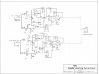
QA400 interface
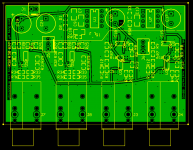
Attached are the expressPCB files for my new version. I have not fully checked these files so if someone else is up to the task it would be great. Expresspcb is not really easy for this denser surface mount stuff. Everything is connected and I don't think there are any shorts. If anyone else is up for loading the files into expressPCB and checking for mistakes I would really appreciate it. I will get a set of PCB's ordered in a week and see how successful I was.
This is way more complex and involved than the first gen. Don't feel bad if you find the schematic or the layout hard to follow. I also find this one challenging. I'm trying to use the latest ideas on ground planes, bypassing etc, even though they probably are not significant at the audio frequencies involved.
Attachments


This is way more complex and involved than the first gen. Don't feel bad if you find the schematic or the layout hard to follow. I also find this one challenging. I'm trying to use the latest ideas on ground planes, bypassing etc, even though they probably are not significant at the audio frequencies involved.
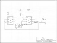
Just curious why you chose to use the charge pumps for the split rails? Are ripple and noise not a concern here?
In my testing and in the previous generation using a switcher the supply noise is not an issue. There is enough PSRR to meet -150 dB noise levels without a problem. Grounding is important or the noise can appear across the grounds. When I have boards I'll be able to verify that the noise of the charge pump won't couple back in.
The switcher on the first gen is too pricey ($15) and sucks too much power all by itself. That and simplifying is why I chose this solution. If there is an issue my fallback will be to use a clockable charge pump and lock it to the word clock. We will all know soon.
The switcher on the first gen is too pricey ($15) and sucks too much power all by itself. That and simplifying is why I chose this solution. If there is an issue my fallback will be to use a clockable charge pump and lock it to the word clock. We will all know soon.
Hello Demian,
Looks good, on the face of it. Does ExpressPCB have a CRC checking and netlist checking against the schematic?
jan
Looks good, on the face of it. Does ExpressPCB have a CRC checking and netlist checking against the schematic?
jan
Demian,is it true that you use the different OP at both outputs at the 1st schematic?Attached are the expressPCB files for my new version.
That was never part of this. The adapter-cables do the scaling as necessary. Since the QA400 would not know about the autoranging you could get really confusing results.
From what Matt has leaked about his next effort it seems time to make the QA400 useful as is and wait for a more capable device if you want. Expect it to be 4X-5X the cost of a QA400.
My goal with this was to get differential inputs and self balancing outputs with higher levels that would be compatible with home audio levels. And to be able to fit it inside the box.
That's a typo. I'll be trying several devices to see what works the best and still is cost effective. Fortunately the footprints are common. I may rescale the impedances to lower the noise.Demian,is it true that you use the different OP at both outputs at the 1st schematic?
From the Pete Millet Soundcard thread -- a little incandescent bulb in the input to protect -- i tested out one from RS and there was, essentially, no contribution to THD measured on the AP.
What happened to the input auto-ranging idea?
-RM
I have layed out a board with a small ucontroller to run a Boonton input board as autoranger. Just waiting for my next board order to tack it on.
The board also has an RMS converter and a small LCD so I can actually display RMS signal value and attenuation setting. I plan to use the Boonton overrange comparators (with modified thresholds probably) as 'too high' - 'too low' sensors.
Jan
😎🙂
I have layed out a board with a small ucontroller to run a Boonton input board as autoranger. Just waiting for my next board order to tack it on.
The board also has an RMS converter and a small LCD so I can actually display RMS signal value and attenuation setting. I plan to use the Boonton overrange comparators (with modified thresholds probably) as 'too high' - 'too low' sensors.
Jan
Jan:
Did you notice that the original designer of the 1120 joined and started to contribute? http://www.diyaudio.com/forums/equi...distortion-analyzer-tweaks-2.html#post3962113
- Home
- Design & Build
- Equipment & Tools
- QuantAsylum QA400 and QA401