@ benb: This is perfectly doable. For another project I developed a temperature control for a quad of capacitors in a precision filter. Good film caps have extremely low distortion but easily have +/-250ppm tempco, which you don't want in a stable precision filter. But it is really not that hard to get down to 0.01 degree stability for a mechanical 'oven'.
I would think that by modulating the reference for such a system, you can modulate the temperature to control frequency.
You could use a phase detector to get the control signal.
Since this is a relatively quite slow process you probably don't need a Peltier element, relying on natural cooling and active heating. If you set it up right, there is continuous heating to compensate for natural cooling, but the rate of heating being continuously adjusted. I love feedback!
And zero control signal intrusion.
But it will be largish, mechanically.
Jan
Last edited:
A very pertinent article! Good find.
Jan
I don't have a direct answer to this, but yes this is critical to it.
The AP can output such a clock, but I don't know about the others.
In any case it should be a relatively straight-forward hack if necessary.
Jan
Update: I checked with one of the AP principals but no definite answer. He did however think that the 'move to bin center' was done after the time domain averaging, which is not helpful with a drifting oscillator.
Jan
I think the check with varying amplitudes vs. FFT length could reveal the leakage. The above linked article used the same method to identify the leakage.
Or looking at the individual FFT bins, of course, if such feature is available.
Or looking at the individual FFT bins, of course, if such feature is available.
The AP 2722 doesn't show the fundamental amplitude in the FFT. The new APx series does; it re-synthesizes the fundamental after the notch and blends it into the spectrum display.
Jan
Jan
?? It is using a PC for analysis, with large LCD and all the assets, and such standard information is not displayed? How much does the toy cost?
We do not need exact value before the notch, just the FFT'd value of the fundamental bin - it should not change with varying FFT lengths.
Clearly there is a need for an open source suite of audio analysis blocks, similar to GNU Radio. BTW that project alone as is would provide quite a lot of features, it supports the soundcard interface. IMO only some audio-specific out-of-tree modules would be needed, e.g. in python OutOfTreeModules - GNU Radio . But most likely all such modules already exist.
GNU Radio is a widely used project for signal analysis, e.g. Guided Tutorial Introduction - GNU Radio , Spectrum Analysis using MATLAB and GNU Radio | Nutaq . I can imagine having shared configurations for various measurement scenarios, including screens with the GUI components.
Logical would be calculating the signal level in DMM from samples directly, not using FFT.
But how about using a regular spectrum display, without the notch filter? The FFT method used by AP should be the same. We do not need the harmonics, just the fundamental.
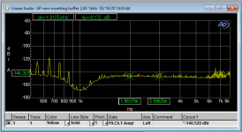
There is no fundamental on your screenshot down to -170dB, does the notch really reject so much or is the fundamental removed from the chart by the AP software?
But how about using a regular spectrum display, without the notch filter? The FFT method used by AP should be the same. We do not need the harmonics, just the fundamental.
There is no fundamental on your screenshot down to -170dB, does the notch really reject so much or is the fundamental removed from the chart by the AP software?
Well, in this case I was using the external passive twin-tee, hence the -170. I did set the reference to 0dBV so it shows the fundamental referred to that 0dBV, attenuated by my external twin-tee and it's own internal notch. But the principle is the same.
AP has evolved from a purely analog architecture to where it is now, so there is a heritage.
The input is an autoranging/gain circuit, followed by analog level metering and a selection of filters and/or the notch. After that, the signal goes to the ADC.
Using the external 40dB twin-tee means that the dynamic range requirements for that ADC is lowered by 40dB, thus the very low distortion limit.
Jan
Last edited:
Has anyone built the 0.5ppm Linear tech Oscillator? IIRC its fixed at 5kHz. I was wondering if say 4 could be built for an instrument - 1kHz, 5 kHz and then 19 and 20 for the IMD that Bob likes. You could then just switch between them. I'm up to do a PCB in a few weeks after I've finished my latest phono amp.
I recall a Bob Pease article where he used a PID in a temperature regulation feedback loop, and claimed to keep temperature stable within 0.001 degree. The title surely starts with "What's all this temperature ..."@ benb: This is perfectly doable. For another project I developed a temperature control for a quad of capacitors in a precision filter. Good film caps have extremely low distortion but easily have +/-250ppm tempco, which you don't want in a stable precision filter. But it is really not that hard to get down to 0.01 degree stability for a mechanical 'oven'.
I would think that by modulating the reference for such a system, you can modulate the temperature to control frequency.
You could use a phase detector to get the control signal.
Since this is a relatively quite slow process you probably don't need a Peltier element, relying on natural cooling and active heating. If you set it up right, there is continuous heating to compensate for natural cooling, but the rate of heating being continuously adjusted. I love feedback!
And zero control signal intrusion.
But it will be largish, mechanically.
Jan
Krohn-Hite used to build analog oscillators with carefully matched cap and resistor tempcos to properly cancel. These were used for testing navigation gyro's before the days of GPS etc. If you can stabilize the temperature and use the right parts you can get quite good stability. I don't know where you can get those resistors with specific tempco's today but I may be able to chase down some possible sources.
Of course I'm interested!
Thanks!
PM me your e-mail if you want a copy. Its too big to send so I do it through Hightail.
1M FFT at 48kHz samplerate has bin 0.048Hz wide (i.e. 0.024Hz to the next bin) and one round takes 21secs of sampling. Is this stability range practically achievable by temperature or voltage feedback?
Does a PLL or injection achieve pushing the natural resonant (the least distorting, IMO) frequency without raising the distortion? I do not have detailed knowledge of the analog-world principles but the technical feeling tells me if something is pushed out of its "natural pace" it will start distorting because every cycle it tries to return to its natural pace, yet it's "kicked" again and again.
The THDs of the freewheeling oscillators being presented here are < -140dB, every imperfection will ruin it. Aiming for less with all the complexity involved seems a bit low-specs target to me. IMO a properly designed, implemented and compensated DAC has a potential of reaching -130dB THD sine, with all its advantages for further analysis. Just contemplating...
I think you need only extremely small 'pull'. For instance, if the oscillator is 1002.6Hz, you could use an ARB set to the same frequency and use minimal injection to keep it from drifting. Then use the same frequency for the ADC sampling and FFT. Wouldn't that work?
BTW I asked Vic for another one of his oscillators to experiment with syncing.
Jan
BTW I asked Vic for another one of his oscillators to experiment with syncing.
Jan
Last edited:
A comparison of multiphase rectifiers for oscillator agc
The AGC (or leveling) circuits in most oscillators are responsible for most of the oscillator distortion if very low-distortion operational amplifiers are used. The two main components of the AGC circuit are the rectifier and the gain control device. The latter is often implemented with a JFET (or other voltage controlled resistance – VCR – element). Both of these components create distortion, sometimes one dominating more than the other depending on circuit details. Here I would like to say a few words about the creation of distortion by the rectifier circuit, and ways to mitigate it. The ripple of its filtered output is responsible for distortion by modulating the resistance of the VCR element.
There are other approaches to the required amplitude detection circuit that offer lower ripple than an ordinary rectifier, the most well-known of which is a sample-and-hold circuit. The S-H can provide very good results, but it can be complex, sensitive to timing of the sampling, and dependant on a fairly small sampling aperture. Unless a dual S-H running off of both the positive and negative signal phases is used, whatever ripple it creates is only at 1X the fundamental frequency. All things considered, it can provide very good performance if carefully implemented, but is not necessarily the answer to the maiden’s prayer.
Here I’ll stick with ordinary rectifier types that are simple to implement and are very forgiving in nature. In particular, I’ll show some ripple data from three different rectifier types. These I will refer to as multiphase rectifiers. I refer to a half-wave rectifier as a single-phase rectifier, since it conducts on only 1 phase of the signal and its ripple frequency is 1X the sine wave input frequency. A full-wave rectifier is a 2-phase rectifier.
When implementing an oscillator as a state variable oscillator (SVO), both in-phase and quadrature versions of the signal are readily available. If these two signals are each presented to their own full-wave rectifier (FWR) and the rectifier outputs are summed, a 4-phase rectifier circuit results. Its ripple is very helpfully at 4 times the fundamental frequency, so a given amount of filtering results in much less ripple.
An 8-phase rectifier is implemented in a straightforward way by properly creating versions of the fundamental that are 45 degrees apart. This is easily accomplished with two resistive summing networks that sum equal portions of the fundamental and quadrature signals. Four fundamental signals now result. If these are applied to 4 FWRs, and the results summed (easily by a resistor network of 4 resistors), then an 8-phase (8X) rectifier results. Its ripple frequency is at 8X the fundamental, reducing even further the ripple for a given filter circuit.
There is another matter at work in reducing the ripple as well. The raw unfiltered output of the FWR falls all the way to zero at the signal zero crossings. This creates a lot of ripple to be attenuated by the filter. The raw output of a 4X rectifier does not fall in its valley nearly as far from its peak because the output from the neighboring quadrature-driven FWR comes up to take over while the raw signal is still at a high level (just 45 degrees from its peak point). By the same process, the raw output of the 8X rectifier falls even much less from the peak, creating a raw peak-to-valley voltage that is much smaller. The valley occurs only 22.5 degrees from the peak in time.
A measurement was done in simulation to illustrate the remarkable improvement in ripple when going from 2X to 4X to 8X rectification. A 1 kHz signal of 5-V peak amplitude was applied to the rectifiers. All rectifier outputs were equipped with the same simple first-order R-C filter with a time constant of 3.3 ms. As a baseline, the filtering was chosen so that the 2X rectifier yielded p-p ripple of 100 mV. Gains of all of the rectifiers were normalized to produce the same rectified DC output level of 3.18V.
The raw rectifier output voltages had p-p voltage swings of 5 V, 1.03 V and 0.21 V for the 2X, 4X and 8X rectifiers, respectively. This is an approximate 5:1 reduction in raw ripple for each doubling of rectifier order (14 dB).
Filtered output p-p ripple voltages were 100 mV, 10 mV and 1.2 mV, respectively. This is an approximate 10:1 reduction in filtered ripple for each doubling of rectifier order (20 dB per doubling of order).
These are exceptionally encouraging results for the high-order rectifiers. This performance is especially important for lower-frequency oscillators (like 20 Hz), but still makes a remarkable improvement for a 1 kHz oscillator. The much higher ripple frequency also invites the use of higher-order ripple filters without serious degradation of oscillator agc stability. I’ll show some results in another post.
Some may think the cost and complexity of the 8X rectifier is high. I don’t think so, given what it does for you. Apart from a couple of resistors, it requires 4 full-wave rectifiers. Each FWR requires 2 op amps, 2 diodes and 3 resistors. The rectifier op amps need not be audio-grade. Even a lowly LM324 can do quite well at audio frequencies in a rectifier application. One quad op amp will give you 2 FWRs. Two quad op amps will do the whole job. Op amps, diodes and resistors are cheap these days.
Cheers,
Bob
I implemented a 4 phase rectifier with LM339's (open collector) as active perfect diodes some time ago. The other virtue of this is that you can get an H2 and H4 signal that can be added back to null out harmonics. This is a trick borrowed from the Amber 3501 oscillator.
Still I think David's trick using an ADC to sample and a multiplying DAC as a gain control is really elegant and simple. Using a fast comparator to sense the zero crossing to trigger the ADC to sample the peak of the cosine is not too difficult to implement. The issue with any of these is to keep any switching transients from getting back into the output. Possibly several isolated supplies would be needed once you are getting below -120 dB since it would not take much crosstalk to show in the output. That is the limitation of the older KH oscillators.
Still I think David's trick using an ADC to sample and a multiplying DAC as a gain control is really elegant and simple. Using a fast comparator to sense the zero crossing to trigger the ADC to sample the peak of the cosine is not too difficult to implement. The issue with any of these is to keep any switching transients from getting back into the output. Possibly several isolated supplies would be needed once you are getting below -120 dB since it would not take much crosstalk to show in the output. That is the limitation of the older KH oscillators.
Hmm,
Why not using this:
The LTC®1966 is a true RMS-to-DC converter that utilizes an innovative patented DS computational technique. ... Unlike previously available RMS-to-DC converters, the superior linearity of the LTC1966 allows hassle free system calibration at any input voltage.
Hp
Why not using this:
The LTC®1966 is a true RMS-to-DC converter that utilizes an innovative patented DS computational technique. ... Unlike previously available RMS-to-DC converters, the superior linearity of the LTC1966 allows hassle free system calibration at any input voltage.
Hp
- Home
- Design & Build
- Equipment & Tools
- Low-distortion Audio-range Oscillator