I have finished the construction of my second-generation low distortion oscillator several years ago. Finally I found the time to collect the performance measurements of it in a document:
low_distortion_oscillator_performance.pdf
So far I have only THD+N and amplitude flatness measurements available. I hope to run THD spectrums in the future, but there are plenty of other priorities in life.
Samuel
low_distortion_oscillator_performance.pdf
So far I have only THD+N and amplitude flatness measurements available. I hope to run THD spectrums in the future, but there are plenty of other priorities in life.
Samuel
I have finished the construction of my second-generation low distortion oscillator several years ago. Finally I found the time to collect the performance measurements of it in a document:
low_distortion_oscillator_performance.pdf
So far I have only THD+N and amplitude flatness measurements available. I hope to run THD spectrums in the future, but there are plenty of other priorities in life.
Samuel
Congratulations, Samuel. These look like great results.
I'm guessing when you get to measuring the residual from the AP with a spectrum analyzer you will no longer have to perform the noise subtraction. Is that right?
Have you considered looking at the THD at two spot frequencies, like 1 kHz and 20 kHz, using a notch filter, like a passive or active twin-T? This would take most of the AP shortcomings out of the picture.
I don't recall where the oscillator design is documented. Can you point me to it?
Cheers,
Bob
bob: Lots here on SG's oscillator: Analog Circuit Design · Samuel Groner · Resources · Low Distortion Oscillators
bob: Lots here on SG's oscillator: Analog Circuit Design · Samuel Groner · Resources · Low Distortion Oscillators
Thanks! This is an impressive body of work!
Cheers,
Bob
For THD, yes. I was also interested in checking the THD+N as I find looking at the THD+N residual on a 'scope (synchronized to the fundamental) to be very informative.I'm guessing when you get to measuring the residual from the AP with a spectrum analyzer you will no longer have to perform the noise subtraction. Is that right?
I have a set of decadic passive notch filters (the documentation for these is on my webpage, see the link that Demian posted above) that I intend to use for THD measurements. Finding a weekend without other priorities is the issue. 🙂Have you considered looking at the THD at two spot frequencies, like 1 kHz and 20 kHz, using a notch filter, like a passive or active twin-T? This would take most of the AP shortcomings out of the picture.
On my webpage (again see the link that Demian posted above) there's the documentation for my first-generation design (May 2010). The measurements I've posted yesterday are for my second-generation design which so far I haven't made public. It follows the same basic architecture as the first-generation design but is more efficient in terms of cost and size, fixes many issues, and adds more features.I don't recall where the oscillator design is documented.
The key architecture features are:
- state-variable RC oscillator with 10 Hz to 100 kHz frequency range;
- peak-sampling amplitude control loop with Gilbert-cell multiplier;
- composite opamps in the main signal path;
- balanced and unbalanced output up to +30 dBu (balanced) and +24 dBu (unbalanced);
- injection-locking option to snychronize the oscillator to an external sinusoidal reference.
How successful is the injection locking? Have you found any significant degradation in its performance?
How successful is the injection locking? Have you found any significant degradation in its performance?
I have been doing numerous very long simulations on injection locking lately. I do not yet have a definitive result, but my current impression, which is probably controversial, is that a perfect, distortionless oscillator cannot be injection locked. I've been comparing simulations of two oscillator designs, one pretty good and one very excellent one. I've been looking both at the time required to lock and the injection level required to lock in a given amount of time. It appears that the oscillator with higher distortion locks faster and more easily. These oscillators are state variable designs implemented with ideal op amps with low-distortion agc loops and carefully compensated JFET agc elements. They differ only in the type of agc rectifier (full wave vs 8X).
In every case, I pull the oscillator by a rather small amount. Its natural simulated frequency might be, say, 1002 Hz, and I try to pull it to the LTspice source frequency of exactly 1000 Hz. The output of the oscillator is passed through a very finely-tuned twin-T notch centered at exactly 1kHz with a very deep depth. I then look at the output of the notch in amplitude, waveform and spectra. Some of the longer simulations are for 2500 cycles.
It takes a long time for the output of the notch to ring down to its final value after injection begins, and whether it really locks before that is difficult to discern. In coming simulations, I will add a phase detector circuit to the simulation to see if that gives a better indication of lock. It seems possible that the oscillator may lock before the output of the notch rings all the way down. I'm looking at a 3V oscillator signal that rings down to a couple of uV peak.
The bottom line I suspect is that injection locking of an oscillator depends on there being some nonlinearity in its implementation. Afterall, apart from the agc circuits, an oscillator built with ideal distortionless op amps (as I used in the simulation) is an entirely linear system.
Stay tuned (pun intended).
Cheers,
Bob
Bob,
Try using an led/photocell to shift the frequency a very small amount and to get the correction use a phase detector on the low distortion oscillator compared to the desired reference!
ES
Try using an led/photocell to shift the frequency a very small amount and to get the correction use a phase detector on the low distortion oscillator compared to the desired reference!
ES
Bob,
Try using an led/photocell to shift the frequency a very small amount and to get the correction use a phase detector on the low distortion oscillator compared to the desired reference!
ES
Yes, basically a phase-locked loop 🙂.
Cheers,
Bob
I haven't investigated the detailed performance degradation, but the circuit is designed for a very narrow lock range (IIRC 0.1% of the fundamental frequency) to reduce the sensitivity to noise and distortion from the external reference. With direct measurements using the SYS-2722 analyzer, the only detectable change is a jump to the exact frequency.How successful is the injection locking? Have you found any significant degradation in its performance?
Analysis and design of autonomous microwave circuits by Suárez offers a detailed treatment of injection locking, but the mathematics is involved and only the strongly non-linear RF and microwave oscillators are considered.I have been doing numerous very long simulations on injection locking lately. I do not yet have a definitive result, but my current impression, which is probably controversial, is that a perfect, distortionless oscillator cannot be injection locked. I've been comparing simulations of two oscillator designs, one pretty good and one very excellent one. I've been looking both at the time required to lock and the injection level required to lock in a given amount of time. It appears that the oscillator with higher distortion locks faster and more easily. These oscillators are state variable designs implemented with ideal op amps with low-distortion agc loops and carefully compensated JFET agc elements. They differ only in the type of agc rectifier (full wave vs 8X).
In every case, I pull the oscillator by a rather small amount. Its natural simulated frequency might be, say, 1002 Hz, and I try to pull it to the LTspice source frequency of exactly 1000 Hz. The output of the oscillator is passed through a very finely-tuned twin-T notch centered at exactly 1kHz with a very deep depth. I then look at the output of the notch in amplitude, waveform and spectra. Some of the longer simulations are for 2500 cycles.
It takes a long time for the output of the notch to ring down to its final value after injection begins, and whether it really locks before that is difficult to discern. In coming simulations, I will add a phase detector circuit to the simulation to see if that gives a better indication of lock. It seems possible that the oscillator may lock before the output of the notch rings all the way down. I'm looking at a 3V oscillator signal that rings down to a couple of uV peak.
The bottom line I suspect is that injection locking of an oscillator depends on there being some nonlinearity in its implementation. Afterall, apart from the agc circuits, an oscillator built with ideal distortionless op amps (as I used in the simulation) is an entirely linear system.
In the lab, out-of-lock conditions are very easily detected. The amplitude control loop immediately looses lock, and the beat note is visible on the multiplier control voltage.
Samuel
Bob,
Try using an led/photocell to shift the frequency a very small amount and to get the correction use a phase detector on the low distortion oscillator compared to the desired reference!
ES
I did some more measurements this weekend on the tracking notch, indeed using NLS-32R3 LED/CDS photocell. It appears that with a signal level of not much above 1V, and a tracking range of about +/-0.3%, I can bring the FFT lines below -140dBc over the tracking range. Voltage across the CDS should stay below 20mV.
I used a pair of CDS cells in parallel to get lower resistance levels, placing the CDS cells in anti-parallel hoping to cancel some of the 2nd harmonic they generate. But funny enough, it is the 2nd harmonic that I see with higher levels, not the 3rd. Maybe the cells should be matched for this to work.
The tracking system uses a phase discriminator similar to the one you used Bob in your 1984 THD analyzer.
I was thinking, would it not be possible to use a notch in the SV loop to force the frequency? Then, tuning the notch would tune the oscillator, only needed in a small range. You would be modifying the frequency where the closed loop gain was just enough to sustain oscillations with the AGC untouched, and the notch distortion could be kept very low. Maybe just a wild idea.
Jan
I haven't investigated the detailed performance degradation, but the circuit is designed for a very narrow lock range (IIRC 0.1% of the fundamental frequency) to reduce the sensitivity to noise and distortion from the external reference. With direct measurements using the SYS-2722 analyzer, the only detectable change is a jump to the exact frequency.
Analysis and design of autonomous microwave circuits by Suárez offers a detailed treatment of injection locking, but the mathematics is involved and only the strongly non-linear RF and microwave oscillators are considered.
In the lab, out-of-lock conditions are very easily detected. The amplitude control loop immediately looses lock, and the beat note is visible on the multiplier control voltage.
Samuel
The amplitude control loop going out of lock when the injection is unsuccessful in locking the oscillator may be unique to the fact that you are using a multiplier as part of the agc. I don't know. None of the simulations I have done using a conventional amplitude detector and a JFET control element have shown any sign of the control loop going out of lock at any point. Just saying that this phenomena may be dependent on the details of the agc loop implementation. As I mentioned above, I do plan to include a phase detector in the simulation as a possibly better means of detecting an out-of lock condition. One concern is that if one is trying to pull the oscillator by, say, only 1 Hz, it will take the phase detector a long time (maybe a couple thousand cycles of simulation) to reliably show the out-of-lock condition, since the beat frequency between the injection signal and the unlocked oscillator signal may be 1 Hz or less.
Cheers,
Bob
Settling time is affected by the low pass filter following the phase detector. It does not have to be the common RC filter. It can be an active multipole filter for faster settling time.
I did some more measurements this weekend on the tracking notch, indeed using NLS-32R3 LED/CDS photocell. It appears that with a signal level of not much above 1V, and a tracking range of about +/-0.3%, I can bring the FFT lines below -140dBc over the tracking range. Voltage across the CDS should stay below 20mV.
I used a pair of CDS cells in parallel to get lower resistance levels, placing the CDS cells in anti-parallel hoping to cancel some of the 2nd harmonic they generate. But funny enough, it is the 2nd harmonic that I see with higher levels, not the 3rd. Maybe the cells should be matched for this to work.
The tracking system uses a phase discriminator similar to the one you used Bob in your 1984 THD analyzer.
I was thinking, would it not be possible to use a notch in the SV loop to force the frequency? Then, tuning the notch would tune the oscillator, only needed in a small range. You would be modifying the frequency where the closed loop gain was just enough to sustain oscillations with the AGC untouched, and the notch distortion could be kept very low. Maybe just a wild idea.
Jan
Hi Jan,
As you know, my go-to technology is SVOs and SVFs combined with JFETs. Of course many other combinations work as well - I'm just more comfortable with these. With a state variable filter or oscillator, a useful way to control the tuning frequency a bit is to put a JFET in series with the integrator resistor, with its source at the virtual ground of the integrator op amp. The JFET can be shunted with the usual center-tapped resistor to provide the needed gate feedback for low distortion. The JFETs need very little voltage across them to tune the SVF over a small range.
In tuning an SVF, it is desirable to tune them on both integrators, rather than by adjusting the overall loop gain of the SVF. This allows both integrators to operate at their unity gain point at the tuned frequency.
Of course, this brings up the issue of matching between the 2 JFETs, just as it would with a dual CdS approach. However, Linear Systems makes the VCR11 dual monolithic JFET specifically for voltage-controlled resistor applications. Being dual monolithic, both JFETs in it are well-matched. It is ideal for this approach, where you will be driving both gates with the same control voltage. The VCR11 JFETs are not greatly different from a 2N4391.
Also note, that with two JFETs working, one on each integrator, you will need less voltage across each JFET for a given amount of tuning range, leading to lower distortion.
Finally, each JFET is working on a signal that is 90 degrees out of phase with the other one. It is possible that this may further reduce the total distortion contribution from them - but I really do not know the answer to this. I'm tempted to think power addition rather than voltage addition. Here is where aSPICE run might be useful 🙂.
A possible downside point is that there is less filtering of the distortion from the JFETs by the integrators. For example, if the frequency is tuned by changing the global loop gain of the SVF, distortion from the single JFET will be reduced by the low-pass filtering of both integrators if the output of the filter/oscillator is taken from the second integrator. In the dual JFET approach, the distortion contributed by one of the JFETs will pass through only one integrator to the output.
Cheers,
Bob
Settling time is affected by the low pass filter following the phase detector. It does not have to be the common RC filter. It can be an active multipole filter for faster settling time.
Very good point, and the 8X rectifier pushes the ripple out by 2 octaves compared to a full-wave rectifier, making the loop more stable in the face of a multipole filter that can be acting at a higher frequency relative to the fundamental.
If you were referring to the settling time of the output of the twin-T filter output in my injection locking time simulations, I'm not sure that the agc loop is playing a role there, but I could be wrong. I think it is settling time of the oscillator frequency to its final (hopefully new) value after the shock of the small injection signal being applied.
BTW, back at Bell Labs in the mid '70s when we were working on timing recovery schemes for our 274 Mb/s (T4) digital transmission system on coax, we had many strong disagreements over injection locking vs. PLLs. PLLs won out, but the oscillators didn't need to be that linear anyway. That was our last digital system on coax. Our first 44.7 Mb/s (T3) fiber optic system followed shortly around 1976. I was in the PLL camp, and designed the phase and frequency PLL IC used in the FT3 system.
Cheers,
Bob
However, Linear Systems makes the VCR11 dual monolithic JFET specifically for voltage-controlled resistor applications. Being dual monolithic, both JFETs in it are well-matched.
Bob
That's a good tip Bob, thanks.
Edit: they should have a good conversation with their copy writer:
The VCR11N Monolithic Dual, N-Channel, JFET Voltage Controlled Resistor is a direct Siliconix VCR11 Series. It is Ideal for Variable Resistor and Grain Control Applications.
Jan
Last edited:
Starting with the idea presented here:
Low-distortion Audio-range Oscillator
I've now built a prototype of a two-phase peak detector using a half of the LM339 comparator, and a TL072 as the inverter. The original idea was presented here:
Low-distortion Audio-range Oscillator
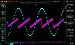
The waveform at the output of the detector is shown in the first attachment. It is a saw wave with a frequency twice the sine wave fed to the detector, and a peak-to-peak voltage of 29mVpp. The inverter gain had to be trimmed in order to produce a clear second phase - I used 1% resistors initially, but that wasn't good enough. According to the simulation, 0.1% resistors should be satisfactory.
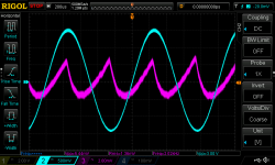
Passing the above saw wave through an 1k/0.47uF LP filter produces the waveform shown in the second attachment. The signal is now reduced by a factor of more than five, but still contains higher harmonics.
The DC part of the signal is -1.49V for the 3Vpp sine
In a next step, I intend to pass this signal through a switched-capacitor filter, which can further attenuate the 2nd by 30dB. The part I have in mind (LTC1062) has a step response of about 2ms (1V step), so a fast reaction of the entire peak detector chain is guaranteed.
I don't have the filter now, but I expect a delivery from Mouser by thursday, and will then present further results.
Regards,
Braca
Low-distortion Audio-range Oscillator
I've now built a prototype of a two-phase peak detector using a half of the LM339 comparator, and a TL072 as the inverter. The original idea was presented here:
Low-distortion Audio-range Oscillator
The waveform at the output of the detector is shown in the first attachment. It is a saw wave with a frequency twice the sine wave fed to the detector, and a peak-to-peak voltage of 29mVpp. The inverter gain had to be trimmed in order to produce a clear second phase - I used 1% resistors initially, but that wasn't good enough. According to the simulation, 0.1% resistors should be satisfactory.
Passing the above saw wave through an 1k/0.47uF LP filter produces the waveform shown in the second attachment. The signal is now reduced by a factor of more than five, but still contains higher harmonics.
The DC part of the signal is -1.49V for the 3Vpp sine
In a next step, I intend to pass this signal through a switched-capacitor filter, which can further attenuate the 2nd by 30dB. The part I have in mind (LTC1062) has a step response of about 2ms (1V step), so a fast reaction of the entire peak detector chain is guaranteed.
I don't have the filter now, but I expect a delivery from Mouser by thursday, and will then present further results.
Regards,
Braca
Attachments
Friends, can I pick your collective brains a bit?
I have been interspersing this thread with posts about my tracking notch filter (and thank you for not protesting that, it could have been considered a bit OT). I am not sure what to do next. The prototype has been proven to work, if the signal level doesn't get too much above 1V all harmonics are just below -140dBc, and it tracks the nominal 1kHz input at +/-3Hz. The reason for my work was to be able to use an external notch filter which tracks an external oscillator for analysis with my AP 2722. (Using an external notch before the analyzer input greatly reduces the AP analyzer self-distortion).
But for best results you really want to do synchronous FFT. The AP can do that with any input freq but a long FFT by definition will loose resolution when the source drifts. That problem is not solved by a tracking notch filter.
That is also why we have been talking here about locking an oscillator to a reference frequency, to be able to do synchronous FFTs.
To complete the tracking notch to the state that a complete project can be published I need to do quite some work. And I am a bit afraid that when I do that, it'll just sit there and have no use. That would be a waste of time and money, but I also suffer from the usual 'sunk cost syndrome'.
So I guess my question is, what would you see as a good use, if any, for a tracking notch ... ? Be honest.
Jan
I'm not trying to troll here or anything bad. I'm just trying to orient myself properly. So, here goes...
What is the goal here?
Is this sort of a *very* interesting hobby of seeing just how low you can make harmonic measurements? There's obviously a lot of satisfaction in being able to push or maybe even advance the state of the art on a measurement technique. Or, pretty much anything, for that matter. That one I appreciate and get the appeal of.
Or, is this attached to some sort of scheme to improve audio performance? This is the part I'm murky on. Even if you go back to the mid 20th century, it was pretty well understood that the IMD spectrum of a non-linear device fairly well overwhelmed the simple harmonic spectrum when multiple tones were applied. Like with audio. Since the linearity of an amplifier varies with frequency - for a ton of reasons people here are well familiar with - being able to measure 1 KHz harmonic distortion down to infinity and beyond may not be all that revealing by itself.
Understanding the problem statement would certainly help me answer whether a tracking notch is useful. It's certainly way cool and an impressive design accomplishment, but I'm not sure why I'd need one.
- Home
- Design & Build
- Equipment & Tools
- Low-distortion Audio-range Oscillator