Hi Richard,
Well, quality is quality. There is no way they compare to the accuracy of even the meter used in the 339A. Each scale is corrected at four points for the movement. This makes them far more accurate to read. Maybe if they used an LED (or LCD) display as well ...
Also, the 339A has an extremely wide passband. Most Asian meters I have seen do not have the HF response required for an accurate reading. My Leader died around 30 Khz even though they claimed 100 KHz response without filters. That was like a kick in the gut for me as I believed what was written as a spec.
Personally, I can't call a 339A over-priced. From what you are saying, even the 331A ~ 334A can probably beat this new one for actual accurate readings. It's that meter and quality of everything else in the box compared to what I have commonly seen in instruments like the one you have copied the picture of.
I wish it were true, but there isn't any point in having newer members believe they are just as good as the real workhorse that was the 339A. Yes, there are better meters out there, and I wish I owned a few of them, but the 339A was a darned good instrument.
Pop the tops on these two THD measurement systems and compare what you see in there.
-Chris")
Well, quality is quality. There is no way they compare to the accuracy of even the meter used in the 339A. Each scale is corrected at four points for the movement. This makes them far more accurate to read. Maybe if they used an LED (or LCD) display as well ...
Also, the 339A has an extremely wide passband. Most Asian meters I have seen do not have the HF response required for an accurate reading. My Leader died around 30 Khz even though they claimed 100 KHz response without filters. That was like a kick in the gut for me as I believed what was written as a spec.
Personally, I can't call a 339A over-priced. From what you are saying, even the 331A ~ 334A can probably beat this new one for actual accurate readings. It's that meter and quality of everything else in the box compared to what I have commonly seen in instruments like the one you have copied the picture of.
I wish it were true, but there isn't any point in having newer members believe they are just as good as the real workhorse that was the 339A. Yes, there are better meters out there, and I wish I owned a few of them, but the 339A was a darned good instrument.
Pop the tops on these two THD measurement systems and compare what you see in there.
-Chris
The specs are not that good and may be a challenge to improve. http://www.nel.com.tr/Eklenti/1767,dtm4120dtm4121pdfcfcd.pdf The company seems to specialize in copies of nearly obsolete instruments: https://sep.yimg.com/ty/cdn/ldb-cdpackaging/CQ620F.pdf Still they may be a good starting point.
I find making a copy of an old instrument kind of a waste of resources. Making a new design with a hybrid of analog and digital would make a lot more sense.
I find making a copy of an old instrument kind of a waste of resources. Making a new design with a hybrid of analog and digital would make a lot more sense.
The specs are not that good and may be a challenge to improve.
Still they may be a good starting point.
Making a new design with a hybrid of analog and digital would make a lot more sense.
Not everyone wants to design and build test equipment from scratch. and battle ship ready build isnt necessary for the hobbyist.
It might be useful as-is to many. Especially if you cant find a 339A in excellent condition and without broken knobs. But I am curious if it is easily upgradable or not and if it is cheap enough. Saw it at 100-200 dollars !!
Then there is this one with .005% range: Audio Distortion Analyzer Zc4137 Digital High Precision Distortion Tester Automatic Distortion Meter - Buy Distortion Meter,Distortion Analyzer,Audio Distortion Tester Product on Alibaba.com
THx-RNMarsh
Last edited:
Serious test equipment always costs more ..... Dont know if that $2200 is a good/best number...
But here is another lower cost unit by same mfr. .01% fs.
Distortion Analyzer In Sound And Audio Measurement Zc4117 Digital High Precision Distortion Meter 300v Sound Analyzer - Buy Distortion Meter,Distortion Analyzer,Audio Analyzer Product on Alibaba.com
And here is source for HP and AP selling direct --->
Audio Analyzer, Audio Analyzer Suppliers and Manufacturers at Alibaba.com
Lots of good new test equipment out there now. Just have to look for it.
Sometimes I just like to push a manual button and get my answer. Thats where hardware comes in handy..... not have everything tying up my PC or having multiple PC running different instruments.
THx-RNMarsh
Last edited:
New price quote = $560 USD
There is an Asian made clone of the HP-339A now. It does not look exactly like the 339A but similar and has all the same features and controls.
View attachment 709451
MCP DTM4120 - distortion meter, View distortion meter, MCP Product Details from Shanghai MCP Corp. on Alibaba.com
I have inquiry in to mfr as to their selling cost.
THx-RNMarsh
Hi All
The HP339A is a great instrument, however is has a few limitations, like BALANCED input (30 volt max), Bridged amps can burn up the instrument and output level 3 volts. Many users find this good for their work while other can’t. Other instruments offer real BALANCED inputs like 200 volts and BALANCED outputs of 26 volts. Great instruments don’t come cheap, used market prices usually out of the investment of most DIY just like Richard said.
My Tek AA501, SG505’s & SC502 & AP Portable One are hardly ever used I typically have 1 or 2 AP running on the bench with 2 or more PC’s. I service & sell used AP’s
Duke
The company seems to specialize in copies of nearly obsolete instruments: https://sep.yimg.com/ty/cdn/ldb-cdpackaging/CQ620F.pdf
Well I can tell just by looking at the pic of the instrument, that the scope's triangle and other waveforms aren't the actual scope pics. They are graphic additions.
It remind's me of the day in a tabloid sized automotive magizene Sharp had a pic of their LCD Projector showing either a car being welded or molten steel being poured. The image was striking and awesome. I contacted their rep in Detroit because I wanted one and we could use it with our client, General Motors.
I was talking with the Sharp rep about the order and asked how they got such great resolution with that projector? They confessed that they didn't, it was an actual picture they used in the ad and that the projector wasn't really as good as in the advertisement. They also confessed that anyone who purchased it was "pissed" that they couldn't get their projected images as good as the one shown and they've been very busy sending people their money back. It was a very bad marketing blunder on their part and advised that I not even buy the product because I too would be sending it back and demanding my money back.
Oh the promise of a great image, I still remember how vivid it was!
Cheers,
@ Steven, BTW do you still have the broken off parts? If so, with some careful planning you might be able to repair it, them:Well I finally found out was is wrong with one of my 339a's. See pix. I think that is Sw4
Epoxy board together.
Re-solder the trace, then smooth it out. Find some broken one somewhere and buy it cheap. ID which units you have/had functioning at their best then move parts around to those and have a dedicated parts unit. There was a guy here in Dallas that had removed some of these switches from his HP units but he wouldn't sell any of them--I asked. I don't know what he did with the ones he had or even if they were the correct configuration for the broken wafers.
Bummer, late to the party, but hey it's still a part nether-the-less (NTL).
Cheers,
Eight months later...
Hi sync,
I actually did buy another HP339a just recently. It has mediocre cosmetics, as every knob is broken or badly epoxied together and two are missing. Upon testing and looking inside, I find the internals look immaculate, like it just left the factory, but the set has an 11.0% - 12.0% distortion at most frequencies.
Using an external 1 khz. signal, from an Amber 3501, the analyzer section reads about -89dB (bouncing between -88 and -91) or around 0.0035% which is certainly in the proper range, so this HP339A has an Oscillator problem.
I just checked the 4 main power supplies - very close to +/-15 volts, and ripple between 0.4 mv and 1.2 mv. Considering that my Fluke shows 0.4 mv between two ground points on the PS board, the ripple may be lower, I am not in a shielded room, just in the dining room.
I checked temps in the set, with ambient at 79.6F most parts were 81 - 102.5 degrees, nothing seemed hot, worst was Q300 at 102.6 degrees. C306 was a bit hotter than the other 3 main caps in that area, so maybe a couple of lytic caps may be due for a change.
So I ruled out the power supplies, and the Analyzer, there is no evidence of prior repairs, but some trace of residue, like someone sprayed a "freezing spray" in a few areas (like at E1 and E2). I have to check the output on a scope, at the A1U1 test point, it is way distorted at the output bananna jack's on the front panel. I had bought a bunch of the LT1468CN8's from Digikey about a year back, and I have a few AD-747's which are similar too if it is a U1 that is the problem, but that is not even close to being verified.
Anyone with some suggestions, where to look next, I would be grateful for the help!
Steven
Last edited:
Hi Steven,
I can try to help.
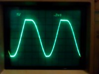
As you mentioned, a peek at A1-TP1 would be a great first look. You didn't describe the appearance of the distorted waveform at the oscillator output, but I'll guess it's clipping on both positive and negative peaks. And most likely a problem in the oscillator amplitude control loop.
Would you describe what you observe at TP1 and at the various test points in the amplitude control loop, i.e. TP3,4,5,6,8? DC voltages, AC amplitudes, and waveform shapes are all of interest.
Good luck!
P.S. BTW, make sure to use a x10 scope probe. X1 probes with their high capacitance can provoke opamp oscillation.
I can try to help.
As you mentioned, a peek at A1-TP1 would be a great first look. You didn't describe the appearance of the distorted waveform at the oscillator output, but I'll guess it's clipping on both positive and negative peaks. And most likely a problem in the oscillator amplitude control loop.
Would you describe what you observe at TP1 and at the various test points in the amplitude control loop, i.e. TP3,4,5,6,8? DC voltages, AC amplitudes, and waveform shapes are all of interest.
Good luck!
P.S. BTW, make sure to use a x10 scope probe. X1 probes with their high capacitance can provoke opamp oscillation.
Last edited:
A few days later, distorted HP 339a
Hi BSST
OK, I have the set and a Sony 336 scope setup and I am using the 50 MHz. 10x scope probe within the A1 osc area.
Probe is currently calibrated and the Sony AC coupled.
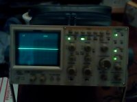
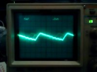
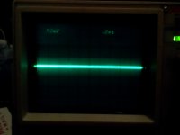
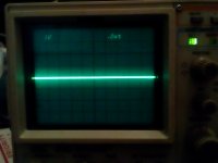
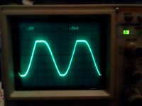
Going to show waveforms on the testpoints. The photos in order are:
Front of Sony 336 scope
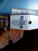
Body of Tek P6148 probe
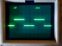
Cal signal optimized on probe
TP1
TP4
TP5
TP6
TP8
(Somehow I lost TP3 when uploading them, hmmm.) Is it needed?
Steven
Hi BSST
OK, I have the set and a Sony 336 scope setup and I am using the 50 MHz. 10x scope probe within the A1 osc area.
Probe is currently calibrated and the Sony AC coupled.
Going to show waveforms on the testpoints. The photos in order are:
Front of Sony 336 scope
Body of Tek P6148 probe
Cal signal optimized on probe
TP1
TP4
TP5
TP6
TP8
(Somehow I lost TP3 when uploading them, hmmm.) Is it needed?
Steven
Attachments
-
 Sony 336 Front.jpg573.8 KB · Views: 236
 -
 Sony TEK P6148 Probe.jpg553.6 KB · Views: 238
 -
 Sony 336 CAL.jpg538 KB · Views: 234
 -
 HP339a TP1.jpg495.1 KB · Views: 227
 -
 HP339a TP4.jpg511 KB · Views: 227
 -
 HP339a TP5.jpg323.9 KB · Views: 53
 -
 HP339a TP6.jpg481.1 KB · Views: 52
 -
 HP339a TP8.jpg498.6 KB · Views: 58
Last edited:
Hi Steven,
David is right. DC voltages will be more telling at this point. Even voltmeter readings may suffice.
TP8 DC volts will tell us a lot. A wild guess is that TP8 will be a large negative voltage.
If so, a couple simple experiments:
If you use a grounded meter probe (or similar technique) to short the junction of R52 and C30, the oscillator should stop. (I've seen lots of warnings to not short Q2 case, so exercise caution.)
Similarly, if you ground TP8, the oscillator should also stop, as that will put Q2 into a low resistance state. If these tests behave as they should, then Q2 is probably OK. Would then measure U2C voltages at pins 12, 13, 14?
Last edited:
Hi Steven,
I’m having erratic internet access at home and am uncertain I’ll be able to get onto the forum this evening. So I’m going to outline some thoughts and offer a few tips.
Based upon the TP8 scope waveform in your post, my best guess is that Q2 is biased into the off state, hence the guess that TP8 will have a large negative voltage near the -15V rail. The “short-to-ground” tests I suggested earlier are intended to test health of Q2, assuming TP8 is in fact a large negative volts as imagined. If TP8 is large and positive, Q2 is likely open, but I doubt this failure mode because of the TP8 waveform.
If Q2 is confirmed operable, the most likely culprit is U2 and the hope is to catch it “misbehaving” in-circuit. To this end, I suggest re-measuring the test points with DC coupling on the scope. Given that the oscillator is in clipping/overload, the anticipated waveform at TP4 is a replica of the TP3 ripple but larger in amplitude (x 2.47) and riding on a DC voltage of several volts. (BTW, once the oscillator is working properly, the saw tooth ripple will remain but average voltage at TP8 will be 0V.) If you don’t see a waveform approximately as described, U2 is highly suspect.
If U2A works correctly, I suggest exercising U2B and U2C using a troubleshooting technique I use frequently:
To test U2B, try to position your scope probe (or voltmeter probe) so that it joins pins U2 pins 6 and 7 simultaneously. This converts the stage into a unity gain opamp. The measured voltage should be a replica of the voltage of the + input--- in the case of the U2B integrator, 0V. Similarly, shorting together pins 13 and 14 should generate a replica of the TP6 waveform.
I hope some of this will point to the problem. Please let me know what you observe/find. Good luck!
- Home
- Design & Build
- Equipment & Tools
- HP339A distortion analyser