Another mod in its place...
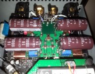
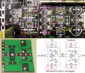
I have tested and finally finalize it the I/V & final stage for unbalanced output.
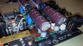
Gold plated (last but not the final version either...") ) 4 layers board, OPA1632 for I/V and Muses8920 for final buffer. TPS7A49/30 for regulators, each pair for I/V and final, with a quite strong filtering...
) 4 layers board, OPA1632 for I/V and Muses8920 for final buffer. TPS7A49/30 for regulators, each pair for I/V and final, with a quite strong filtering...
The board it have differential/balanced outputs too (back side), but not used in this setup. This option it may be redundant for Oppo 105/105D, but it was designed for Asus ST/STX sound card application...
This board it have two more versions suitable for LME49990 use, as for both stages (all chips) Muses ones. Well, not tested yet...
No any HF filtering in this approach. The only filtering (further a little bit controversial) a film cap between DAC output phases. This cap still worse the HF residual level on RCAs, but in the same time it bring a quite spectacular precision for the sound elements in the soundstage, while giving larger space to the soundstage.
Well, Muses chip may not a standard configuration, but an experiment in this setup. Muses it make the sound sounding in a special pleasant way. I like it, but I can not say that is the last/definitely choice...
Again, the large decoupling caps do a very good job for the resulting sound, even though are placed after these very good low noise regulators.
BTW, this board it may be available to those interested. The design is quite simple, and the regulators it use the datasheets schematics and recommended components. There are some internal traces, but not important for understanding of the placement of the components. The opamp stages are even more simple, and does not need a special schematic for placement of the right components (recommended or own approach). So, an eventual user can populate as one want this board (for specified above active components). As final buffer it can be used Muses, LM6172, or any similar...
I have tested and finally finalize it the I/V & final stage for unbalanced output.
Gold plated (last but not the final version either...
) 4 layers board, OPA1632 for I/V and Muses8920 for final buffer. TPS7A49/30 for regulators, each pair for I/V and final, with a quite strong filtering...The board it have differential/balanced outputs too (back side), but not used in this setup. This option it may be redundant for Oppo 105/105D, but it was designed for Asus ST/STX sound card application...
This board it have two more versions suitable for LME49990 use, as for both stages (all chips) Muses ones. Well, not tested yet...
No any HF filtering in this approach. The only filtering (further a little bit controversial) a film cap between DAC output phases. This cap still worse the HF residual level on RCAs, but in the same time it bring a quite spectacular precision for the sound elements in the soundstage, while giving larger space to the soundstage.
Well, Muses chip may not a standard configuration, but an experiment in this setup. Muses it make the sound sounding in a special pleasant way. I like it, but I can not say that is the last/definitely choice...
Again, the large decoupling caps do a very good job for the resulting sound, even though are placed after these very good low noise regulators.
BTW, this board it may be available to those interested. The design is quite simple, and the regulators it use the datasheets schematics and recommended components. There are some internal traces, but not important for understanding of the placement of the components. The opamp stages are even more simple, and does not need a special schematic for placement of the right components (recommended or own approach). So, an eventual user can populate as one want this board (for specified above active components). As final buffer it can be used Muses, LM6172, or any similar...
Attachments
Last edited:
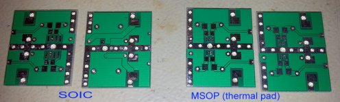
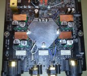
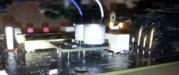
I got today the PCBs for fully differential stage/module. There is a SOIC version, as for MSOP chips.
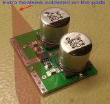
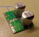
You can see in the pictures a illustration of how it may looks the module populated with components.
The decoupling caps it can be mounted on both sides, as the module can be also placed upside down on the stereo board.
As I will mount myself quite soon these modules on my board, more mounting details with pictures will come in the next few days.
The module is a kind of "universal brick", and it can be used for both I/V stage as for final buffer on balanced lines. The same module it can be used as I/V for unbalanced stage, with the original final buffer in place.
It can be used too as stand alone fully differential amplifier module, and it can easily be adapted to any specific application (post DAC signal processing).
The decoupling caps it can be SMD ones, or any other leaded type.
Some extra differential output connections are provided on the boards, but for applications on 105/105D models, there are not necessary these outputs. All the external connections (inputs, outputs, as power rails) of these modules, it fit exactly the footprints on the player`s stereo board.
The module are available as bare boards, or fully equipped/customized for any specific use. The large via provided on MSOP modules it make very easy the soldering of the chip thermal pad (from the back side). The same soldering technique it can be applied to the SMD decoupling caps.
Attachments
Last edited:
Yes, of course...
The mounting instructions for the fully differential stage/module it will be published here quite soon (as I will mount it myself and take some pictures of the process).
If your question relate to the unbalanced module (with regulators on-board), then the answer is the same, positive too...
For more details, please PM-me.
Last edited:
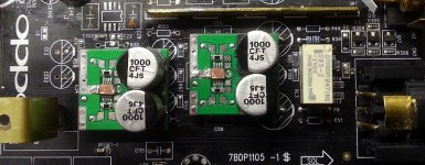
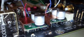
As I was promising, some more informations, pictures and schematic for this mod.
As the pictures are quite explicit about implementation, I will not write more related text in this post, but feel free to ask your questions.
I stated previously that the modules it fit perfectly the footprints on the original stereo board. While mounting the modules, I discovered that this statement is not completely true. I have discovered a little fault in this, which is corrected for the future version of the modules.
The module as it is it fit perfectly for the Final Buffer stage (balanced), but for the I/V it have to have longer connections for the +/- power pins, as these footprints come on opposite side than is designed on the module PCBs. This is really not important for the functionality, but to be just accurate it is corrected in the new version of the module boards. As you can see, I was using myself the module as they are, with fully success.
As I also mentioned, the power rails already exist for these modules, on the stereo board (marked points in the pictures). In my case, when using the unbalanced module, this module it have also its own regulators (TPS7A49/30) on board. I was using these regulators to power my fully differential modules for the balanced stage. With much better results...
Attachments
-
 AllInPlace-Running.jpg866.9 KB · Views: 192
 -
 Bal-UnbalChConnected.jpg588.9 KB · Views: 192
 -
 2chDifAmpMODULES.jpg767.4 KB · Views: 199
 -
 MountedDifAmpMODULES.jpg284.4 KB · Views: 164
 -
 MountedDifAmpMODULES2.jpg446.4 KB · Views: 161
 -
 ModulMounting.jpg129.4 KB · Views: 197
 -
 BalancedStageMOD.jpg811.3 KB · Views: 338
Last edited:
As I mentioned, I was using (experimentally) as filter for unbalanced (new pictured module) film caps over the DAC output phases. Finally I decided to do not use any more such filtering (after I was a supporter of this filtering method).
I think I come once again to the same conclusion I had before (but not very decided on it...).
There is something special with this kind of filtering. Into a certain fidelity level of the system/device/circuit, this filtering cap it give the (psychoacoustic) impression of increasing fidelity, and/or the soundstage resolution. When this filtering is applied to a circuit capable of very high level of fidelity, the result is only bad. Even more and factual, this cap increase the HF noises quite much, but on very high frequencies (Mhz).
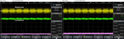
I will demonstrate this with some scope pictures here. The unbalanced noises versus balanced noises. Please note that on balanced lines there are no any caps in the signal path. No any filtering at all. I did not planted caps on my modules used for balanced (as you may see on the pictured modules). The result is just over exceptional.
After removing the caps over the phases for unbalanced stage, it become very difficult to notice the difference between balanced and unbalanced, when about the high level of fidelity, and dynamics. Quite impressive...
I think I come once again to the same conclusion I had before (but not very decided on it...).
There is something special with this kind of filtering. Into a certain fidelity level of the system/device/circuit, this filtering cap it give the (psychoacoustic) impression of increasing fidelity, and/or the soundstage resolution. When this filtering is applied to a circuit capable of very high level of fidelity, the result is only bad. Even more and factual, this cap increase the HF noises quite much, but on very high frequencies (Mhz).
I will demonstrate this with some scope pictures here. The unbalanced noises versus balanced noises. Please note that on balanced lines there are no any caps in the signal path. No any filtering at all. I did not planted caps on my modules used for balanced (as you may see on the pictured modules). The result is just over exceptional.
After removing the caps over the phases for unbalanced stage, it become very difficult to notice the difference between balanced and unbalanced, when about the high level of fidelity, and dynamics. Quite impressive...
Attachments
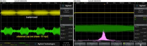
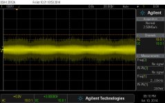
After few fine tunings, I got these noise levels on balanced/unbalanced outputs (no any filtering/caps in the signal path).
There is a 3dB higher gain for the balanced ones, and this is reflected in the noise levels too.
I think it may be acceptable for an outputted approx 15 Vpp useful signal...
There is a 3dB higher gain for the balanced ones, and this is reflected in the noise levels too.
I think it may be acceptable for an outputted approx 15 Vpp useful signal...
Attachments
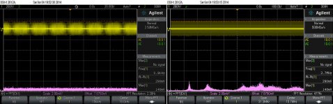
But what is actually this noise?
I was looking myself afterwords at this picture posted above. It is something here which do not make sense...
There is there a 140mVpp/280mVpp signal, which is quite obvious that is modulated. There is for sure a modulated noise. This noise it may have lot of frequencies components. This noise is very specific to the ES9018 chip, and it come out when the chip is up and running. If this noise is to be seen on output, then for sure the chip is working well and right.
But where are the noise frequencies components in the FFT graph?
A FFT (2mV/div) is just flat over a 150khz... Where it may be in FFT graph these noise components which shown/measure 140mVpp/280mVpp per division? Where it may be the modulation component in this FFT? This modulation signal is somewhere in 20ms/50Hz domain... No way to hear it amplified at all...
I could not notice any disturbance whatsoever from such noise (coming out from ES9018 DAC) on the outputted audio signal, even I have measured on outputs a 600mVpp of such noise level?
What is wrong here? The measurements, the interpretation? Or both, or nothing...?
Anybody with some pertinent thought about?
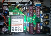
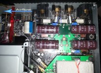
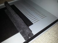
And here is the "ultimate" mod for the fanless 105 model...
While waiting for some answers from the previous posts questions, I come on this...
A 12v fan powered by 5v (USB), which will create and direct a very slightly airflow, from the enclosure up/down openings on the right side of the device, to the cover upper opening on the left side. An airflow guide, made of some textile thing, like a wall in the space between the cover and the disk transport, it will create a separation between right/left openings. This "wall" will contribute to a effectiveness of the airflow circulation.
The under voltage powering of the fan, the very flexible (but enough stable) mechanical mounting, and some damping silicone devices it make the noise/vibration of the fan completely inaudible.
Well, I will not state that the cooling improvement it mean something better for audio stage. I could not notice anything like this... But a better cooling for the processor and the HDMI chip it really bring very noticeable improvements for video/picture quality. The video signal/processing is quite sensible to noises generated by high working temperature of the involved components. Lowering the components temperature it lower its thermal noise levels, and it improve much noise/signal ratio for the video stage.
Quite simple and very efficient...
Attachments
Last edited:
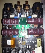
I decided recently to dismiss the headphone stage in my player, as I will never use it. Disconnecting the power from the amplifier chip it unload the main regulators for +/- 15v, and lower its heat dissipation.
The removing of the headphone functionality it free up two pairs of DAC channels, which I have coupled at once, together with the existing balanced ones. Now I have 3+3 DAC outputs for balanced outputs.
I have to say that there is a big difference now between this configuration, compare it to only one pair of channels (for unbalanced lines).
So, why not connecting 4+4 DAC channels to the balanced lines, and that`s it?
And what for use unbalanced outputs, if the balanced ones sounds much better?
So it came the idea to design a complete post DAC processing stage, with integrated both balanced and unbalanced configurations and TPS7A regulators on-board.
It will be so a much compact and small board, than the Oppo original design, and very similar as dimensions with the pictured here one, and it may be used to process a such 4+4 DAC channels setup, for either a unbalanced or balanced configured output. The board it may be populated only for the used configuration, and having the advantage of using very low noise regulators as TPS7A49/30 are...
By the way, I have noticed that in my "no filtering" setup, the residual HF noises (see previous/above posts) it increase when one connect together more of the DAC output channels. I can measure now 550mV such modulated HF noise for these 3 channels connected in parallel. Following this rule, the DAC may output for 4+4 channels in parallel, an even higher noise level... This is not so good perspective...
But the most interesting in all this noise problem, is that there is no whatsoever disturbance for the resulting sound. Just opposite, increasing in fidelity, dynamics, and presence of the sounds... Not so easy to explain all these...
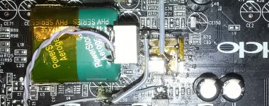
And a last detail: I was using an 0,4F cap to decouple the AVCC of ES9018... And very surprisingly, the LT1763 regulator it accept such huge capacity just fine...
The bass expanding in details and dynamics become just extreme, as the amazing detailed sound in general...
Well, as cons, a such huge capacity may show a quite high ESR/ESI. I could not measure it so far. However, the sound improvements are huge, so why not using it so as it is...?
The removing of the headphone functionality it free up two pairs of DAC channels, which I have coupled at once, together with the existing balanced ones. Now I have 3+3 DAC outputs for balanced outputs.
I have to say that there is a big difference now between this configuration, compare it to only one pair of channels (for unbalanced lines).
So, why not connecting 4+4 DAC channels to the balanced lines, and that`s it?
And what for use unbalanced outputs, if the balanced ones sounds much better?
So it came the idea to design a complete post DAC processing stage, with integrated both balanced and unbalanced configurations and TPS7A regulators on-board.
It will be so a much compact and small board, than the Oppo original design, and very similar as dimensions with the pictured here one, and it may be used to process a such 4+4 DAC channels setup, for either a unbalanced or balanced configured output. The board it may be populated only for the used configuration, and having the advantage of using very low noise regulators as TPS7A49/30 are...
By the way, I have noticed that in my "no filtering" setup, the residual HF noises (see previous/above posts) it increase when one connect together more of the DAC output channels. I can measure now 550mV such modulated HF noise for these 3 channels connected in parallel. Following this rule, the DAC may output for 4+4 channels in parallel, an even higher noise level... This is not so good perspective...
But the most interesting in all this noise problem, is that there is no whatsoever disturbance for the resulting sound. Just opposite, increasing in fidelity, dynamics, and presence of the sounds... Not so easy to explain all these...
And a last detail: I was using an 0,4F cap to decouple the AVCC of ES9018... And very surprisingly, the LT1763 regulator it accept such huge capacity just fine...
The bass expanding in details and dynamics become just extreme, as the amazing detailed sound in general...
Well, as cons, a such huge capacity may show a quite high ESR/ESI. I could not measure it so far. However, the sound improvements are huge, so why not using it so as it is...?
Attachments
Last edited:
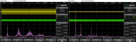
I have connected together all the ES9018 outputs in 4+4 configuration...
I have to say that I never experienced a such dynamic and exceptional sound. I do not have words to express this...
I think I found out why the HF noise is increasing as the DAC outputs channels are connected together. I did these connections without changing accordingly the feedback resistor for the I/V stage. In 4+4 (as for 2+2, or 3+3) configuration the feedback resistor have to decrease as the datasheet recommend. Doing so, I suppose the HF noise at the device outputs it may be quite constant as for 1+1 channels configuration (used for balanced/unbalanced stereo setups in Oppo players).
I have updated the fully differential I/V stage to the new configuration of the DAC output (4+4 channels). The HF noise on XLR outputs is now more than two times lower, and I can see a modified shape of it. I have eliminated the unbalanced stage. This it lowered quite much the heat dissipation of the main regulators. So far so good...
But what about to have a better filtering for AVCC? Like a 2,5 F cap...
The increasing of the details, and dynamics in the low end of the spectre is just remarkable. with this huge capacity in place. The precision of the bass sound elements in the soundscene is unbelievable.
I can hear sounds and noises from the recording in low end of the spectre which I never was aware it can exist in some reproduced recordings. Very, very impressive.
All these in addition to all the good the 4+4 configuration can bring...
Attachments
Last edited:
I may precise something about this measured HF noise on XLR outputs (previous posted picture).
I have measured this between GND and one of the XLR differential outputs. I think it may not be just right result doing this way.
I wonder if this noise it may be actually cancelled by the differential configuration itself...
It may be more relevant to measure the possible HF noises coming out on the speakers outputs of the power amp... But this is almost impossible in my case, as both my scope and the audio system are positioned in stable places quite far from each other...
Any thoughts/comments/suggestions about, or the right way to measure the effective noise on such differential (XLR) output line?
- Home
- Source & Line
- Digital Source
- Oppo's BDP105 - discussions, upgrading, mods...