so the designers of the D1V3 had no idea how to develop a reasonable DAC: balanced PCMs (????) and bags of noise.....Dr.H said:The original DAC did not use a secondary VCXO-PLL.
I used a 74HC174, which allowed me to do the following for each signal:
D creates Q which is fed to D1 whoch creates Q1. I then take the output from Q1.
I did this for all 3 lines in one package. Is this the best way or should I run 3 seperate 74HC74's, once for each line?
Doubling the reclocking only has sence if it has been done in phisically different IC's with different power supplies.
More important is to separate the clock/LE from the DATAL and DATAR-reclocking. If you look at the power-input (16) of the reclocking-IC in wich the data is reclocked, you will find low frequency data-related signals!
Because the delay of the 74HC174/175 depends on the power supply voltage, the power supply at the clock reclocking IC's (especially LE) should be absolutily stable. Audio-info at this point will degrade the jitter performance.
Thanks Herb! 
So you suggest I use a SEPERATE 74HC174 to reclock LE and BCK in one package and then another 74HC174 to reclock DATA only?
Scheme 1
DATA-174(1)-reclocked DATA
LE-174(2)-reclocked LE
BCK-174(2)-reclocked BCK
Would it be better to use a seperate 174 to reclock each line?
Scheme 2
DATA-174(1)-reclocked DATA
LE-174(2)-reclocked LE
BCK-174(3)-reclocked BCK
Dr.H said:Thanks Herb!
So you suggest I use a SEPERATE 74HC174 to reclock LE and BCK in one package and then another 74HC174 to reclock DATA only?
Scheme 1
DATA-174(1)-reclocked DATA
LE-174(2)-reclocked LE
BCK-174(2)-reclocked BCK
Yes Sir, the clock-signals are related to each other and do not influence the power-current so that the power supply point does not change in (long) time.
Even 'cross talk' is not important: if BCLK noises, LE will be noisy as well.
BTW. Do you not use 'stopped clock'?
OK, finally tried the new mode (LE and BCK reclocked in one package, DATA in seperae package) suggested by Herb and it seems to be better.
Thanks Herb.
I have been a bit uncertain about the benefit of the reclocking since the volume is much softer than the unmodified channel;
I have now listened very carefully to highs, mids and bass and in all 3 cases, the sound is cleaner and has more air.
Highly recommended mod!
Thanks Herb.
I have been a bit uncertain about the benefit of the reclocking since the volume is much softer than the unmodified channel;
I have now listened very carefully to highs, mids and bass and in all 3 cases, the sound is cleaner and has more air.
Highly recommended mod!
Dr.H said:I have been a bit uncertain about the benefit of the reclocking since the volume is much softer than the unmodified channel;
Is the sound 'less loud', I mean: is the output voltage lower after the modification, or seems it less loud? In case you should investigate the timing of the clock and the data in the reclocking circuit: the positive edge of the data should arrive before the edge of the clock! (For this you need a 50 MHz oscilloscope....)
I have now listened very carefully to highs, mids and bass and in all 3 cases, the sound is cleaner and has more air.
Wait untill you listen to stereo......... Waaw...
BTW.: are you still using the standard clock in the transport?
Thanks for the advice Herb.
The sound on the reclocked channel is definately softer. I will measure the Vrms to see if it is different to the un-modified channel.
Mmm, I do not have access to a good 50 MHz scope.
I have created a PCB for the reclocking circuit, using 3x74HC174 for two PCM63 DACS (per channel). DATA gets it's own 174, while LE and BCK are reclocked on one.
With the PCB, I'll be able to pay better attention to power supply decoupling.
Still using the transports standard clock... I was hoping to hear from TENTLABS regarding my 11.xxx MHz VCXO order since I want to change it to a 16.xxx MHz XO order, but no news from GUIDO yet....
Herb, would the XO be as good as the XO3.2 if I just used the better clock and not the new SPDIF output?
Dr.H said:With the PCB, I'll be able to pay better attention to power supply decoupling.
The 174 for the DATA and the 174's for the clock's should be decoupled with their own voltage-stabiliser, which should be put on the PCB as close to the 174 in question as possible.
Herb, would the XO be as good as the XO3.2 if I just used the better clock and not the new SPDIF output?
NO! The enhancement of the SPDIF is still necessary. (I hope you also read 'the other thread'....) It is hardly to believe, but it is very well audible. An XO3.2 on 16.xxx MHz? Should I ask Guido?
Dr.H said:Did the second channel on PCB as well. Resolution is amazing. soundstage is wonderful.
Thanks to all you diy geniuses here!
I know that a better clock will get beter results, but that XO3.2 is wayyy to expensive for a hobbyist. I'll get the XO.
Hi
OK for the XO, but make sure to use a low noise power supply and try to reclock the SPDIF signal using that same XO
best
Dr.H said:Hi Guido,
Can I change my order from the 11.xxx MHz VCXO to the
16.xxx MHz XO?
When do you expect to ship the order?
Regards
Ryan
No problem, I mailed you already to do so, the only remaining issue is money: You paid too much since you wanted a VCXO to start with.
best
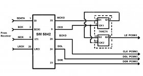
I would like to try simple 2X LE reclocking as per 2. In original post
setup Is based on digital receiver, SM5842 and PCM63 without external XO
Would you please check out attached diagram for errors
I am not sure If passing LE signal through 2 x gates without touching all other signals DOL, DOR, BCK Is correct
setup Is based on digital receiver, SM5842 and PCM63 without external XO
Would you please check out attached diagram for errors
I am not sure If passing LE signal through 2 x gates without touching all other signals DOL, DOR, BCK Is correct
I thought I should post my efforts here for the record and benefit of other digital newbies:
In reclocking the signal between the the 5842 and the PCM63, I tried:
1.Reclocking LE (Latch enable) with a 74HC74 flip flop using CK (pin 9 of 5842): Result was ok.
2. Reclocking LE twice (i.e. 1D-1Q to 2D and output from 2Q) using CK on a 74HC175. Better result than single reclocking
3. Reclocking LE 3 times using 74HC374. much louder than 1 or 2 and lots of detail, but noisy spikes at certain parts of the music;
4. Reclock LE 4 times: Worse noise than 3 and louder than 3.
Using 3x reclock on LE, I then reclocked DATA once-still some noise;
Using 3x reclock on LE, I then reclocked DATA TWICE-noise gone on MOST songs, but still present on some music.
Using 2x reclock on LE, I reclocked DATA and BCLK. Using CK of Sm5842, I got nothing but noise; Using an indepedant 11.xxx clock, I got nothing but noise....
So I have settled on just reclocking LE 2x, using 74HC174. Data and BCLK are not touched.
Any feedback welcome.
Attachments
samoloko,
The purpose of reclocking twice is minimize chances of metastability occurring at the D-FF output.
You would need to look at the signals with a scope to see what is actually happening with your proposed circuit. D-FFs have setup and hold time requirements to pass data reliably. That means WCKO edge would need to have passed and WCKO be at either a stable high or low before the triggering edge of CKO occurs. If all the signals coming out of SM5842 are switching at exactly the same time, then there will not be time for the D-FF Data input pin setup and hold specifications to be met. The only solution might be to delay and or invert one of the signals enough so that the relative phases of WCKO and CKO are correct for predictable D-FF operation.
Regarding the question of whether or not the other signals should get reclocked too, it depends what the scope shows about their timing and what the dac chip likes best in terms of signal timing. The datasheet should contain information about requirements for the digital input signals. If not, and if the dac chip is designed to be used with SM5842 then maybe the dac chip is designed for the signals to be in the same phase relationship as when they leave SM5842. Otherwise, maybe they should be all aligned together. Don't know myself since I haven't spent time with dac chips of that type.
EDIT: Please see the attached document for more info on metastability.
Attachments
Last edited:
Yes. That is like Markw4 said. But it is not only about metastability issues. Whem we clock just one section F-F then output is shifted ont the opposite edge with clocking sygnal. Master clock usually. And if we use later this MCK it will be out of the phase within other lines. Actually other lines will be shifted with 1/2 cycle of MCK that clocks F-Fs.
.
So proper recklocking should consists of 2 cascaded F-F
But as wee can saw this is not the case in most of diy implementations...
.
And clocking F must be at least 2X higher MCK than BCK we want to recklock.
.
So proper recklocking should consists of 2 cascaded F-F
But as wee can saw this is not the case in most of diy implementations...
.
And clocking F must be at least 2X higher MCK than BCK we want to recklock.
Last edited:
No it isn't.Whem we clock just one section F-F then output is shifted ont the opposite edge with clocking sygnal.
That is called Brute Force Synchronization and it is not necessary when the signals in question are in sync. You would definitely not need it with the SM5842 and the PCM63.So proper recklocking should consists of 2 cascaded F-F
- Status
- This old topic is closed. If you want to reopen this topic, contact a moderator using the "Report Post" button.
- Home
- Source & Line
- Digital Source
- Reclocking balanced PCM63