No, not a bit. I think the trick to better digital sound might be to have very low ESR with lots of amps on the digital PS. Most of the regs have some sort of over current protection that allows them to feed the caps until they are charged.
I also use BlackGate HiQ caps as close to the pins of the 1541a as possible. Could be my imagination, but I feel BG and TDA1541a is a match made in heaven.
The TDA current consumption is 50 mA at the most per voltage , that's not really à lot
 , supercaps are totally useless here
the sound you hear is made and shape at the analog side , and what comes out the TDA is 4 mA not a lot too
the digital side make bits , bits that we like to be clean , on time and steady , dont we
.
Last edited:
It certainly doesn't need it to function. Any power supply that can hold +-5V will do. But, to my ear there is a not so subtle impact on sound.
And if you think this is mad, there are a bunch of people building power supplies out of 3000F caps to power their FIFO reclock feeding the I2S signal. It presents a similar load.
https://www.diyaudio.com/community/...te-weapon-to-fight-the-jitter.192465/page-617
And if you think this is mad, there are a bunch of people building power supplies out of 3000F caps to power their FIFO reclock feeding the I2S signal.
It presents a similar load.https://www.diyaudio.com/community/...te-weapon-to-fight-the-jitter.192465/page-617
It's important to me that the bit clock to the TDA is stopped once the data has been latched.The TDA current consumption is 50 mA at the most per voltage , that's not really à lot
the sound you hear is made and shape at the analog side , and what comes out the TDA is 4 mA not a lot too
the digital side make bits , bits that we like to be clean , on time and steady , dont we
.
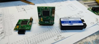
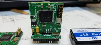
Very interesting @wlowes ! From Wikipedia on supercaps: "can accept and deliver charge much faster than batteries" sounds like an interesting idea for powering the the digital. Have you tried powering the digital front end from supercaps too? Have you tried stacking them up to power -15V line too? Any pictures of your contsruction ?
?It's important to me that the bit clock to the TDA is stopped once the data has been latched.
it is very important to me too
.
I use them in various supplies in the digital front end dealing with iancanada FIFOPi. Mine is a very tame example. Take a glance through ian's thread https://www.diyaudio.com/community/...fight-the-jitter.192465/page-621#post-7672642. He found in increasing order of preference wrt subjective sound quality,Very interesting @wlowes ! From Wikipedia on supercaps: "can accept and deliver charge much faster than batteries" sounds like an interesting idea for powering the the digital. Have you tried powering the digital front end from supercaps too? Have you tried stacking them up to power -15V line too? Any pictures of your contsruction
1. traditional linear power supply with low noise reg
2. Lithium battery,
3. Battery with supercap filter,
4. Large 3000F supercap disconnected from charging source
So mine is a simple cheap hybrid using well filtered linear supply, low noise reg and 1.5F supercap close to the load.
I have not tried supercaps on the -15V. You need a lot of 2.7V caps balanced and it was just not worth it. IMHO the +-5V caps have a more pronounced impact on sound then the -15V line. On the -15V I use linear PS 6th order filter and a salas shunt. After the shunt I use 1000uF BlackGate N in super E config and a BG HiQ cap at the pin. I happened to have them and quite like the sound of BG on the TDA1541a. For completeness all of this is running an S2 variant which I also prefer over std, S1 or R1.
L'adattatore Saa7220 dovrebbe funzionare anche come sostituto semplicemente plug and play del filtro Saa7220 per una modalità NOS... Ha all'interno un orologio per la necessità di un lettore CD. Sarà solo necessario fare dei ponticelli su di esso ed eliminare la rete dell'orologio originale staccando alcuni cavi.
Attachments
While waiting for my PCB's to arrive, here is take two on the filament bias of 2x1541A, taken from the 801A raw filament supply (L-input supply, RCR filter). The parts specified according to what I have/want. In particular, I want a wirewound Bourns 10x potentiometers. Costly item but they are close to the DAC outputs. I'm still trying to figure out if there is any dangerous loop/feedback formed here or not. Two versions of Riv calculated: 18R and 10R.

Ground routing is headache, trying to separate the signal and the 15V biasing supplies. Here is an idea, the worst is the link between the PCB GND and the main start GND of the whole assembly. It carries both the signal and the currents of the 7815's and the surrounding caps. But since the tubes are referenced to the main GND, I think the volatge drop on this link is out of the signal loop. Comments/criticism welcome

Ground routing is headache, trying to separate the signal and the 15V biasing supplies. Here is an idea, the worst is the link between the PCB GND and the main start GND of the whole assembly. It carries both the signal and the currents of the 7815's and the surrounding caps. But since the tubes are referenced to the main GND, I think the volatge drop on this link is out of the signal loop. Comments/criticism welcome
It is not. It is injected, or actually the voltage offset, through the lower 2R resistor. It's John's (ecdesign) idea, which is supposed to be better than connecting the output to +5V pin via 2.2k resistor. Ideally, the +15V supply should be separate but in my situation (the 801A pre is assembled and running) I don't have extra place to make another supply, hence I'm trying to use the raw filament supply.
Look closer - 18R + 2R is the IV
Yes, someone did advise but I do not see much merit in having individual biasing at each chip if the outputs are connected together anyway as pointed out by dddac. If you have any arguments, I'd be happy to listen and consider.
If you make measurement of your setup as it is once completed , and I am sure you will do and post , the distortion figure will tell more than I and dddac will do
.
@fabrice63 you never really answered my question as to what biasing scheme you have (no idea why you are so cryptic about your design which you made with a big help of the community here). But looking at your PCB, it seems you have simply a multiturn pot to +5V, which you later supplemented with a diode. This is a different scheme than the one I'm considering so your observations may or may not apply here.
@batteryman Yes this is also an option but I have to contemplate which one better "screens off" the 7815 from the signal path. IIRC the R_pri of my SUT is 3,5R.
@batteryman Yes this is also an option but I have to contemplate which one better "screens off" the 7815 from the signal path. IIRC the R_pri of my SUT is 3,5R.
- Home
- Source & Line
- Digital Line Level
- Building the ultimate NOS DAC using TDA1541A