No. The point being that using stuff one already has not often leads to optimal design. Your remarks are right but then why the caps are already dangling in the air connected to new RCA connectors? One could have reused the old RCA output holes to fit new ones...
I think transformers are not possible with this DAC chip but I never tried with this DAC specifically. Since I stopped modding CD players and went to solid state playback myself at least 15 years ago I have to check my stuff and circuits, I can come back to that later if you like.
BTW first thing an experienced modder notices is the too low supply voltages of the original output stage. +/- 5V is the absolute minimum and therefor a design error. Certainly with M5218 as it can output +/- 12V with a PSU +/- 15V....It will clip with +/- 5V...
Last edited:
Recapping and adding a low jitter clock are definitely on the list of things to do, I need some guidance to carry them out though. I have lots of caps of various types I could use, I just need to know what to use where for best effect.
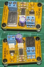
I have a low jitter clock module I could install, it has the correct 16.9344Mhz crystal for this player.
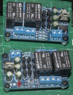
I also have a relay module, it is intended for speaker protection in an amplifier, but I suppose it could be used for muting too?
I have a low jitter clock module I could install, it has the correct 16.9344Mhz crystal for this player.
I also have a relay module, it is intended for speaker protection in an amplifier, but I suppose it could be used for muting too?
Attachments
The problem starts with " I have lots of caps of various types I could use" as you assume you have to change things and the second problem is to want to use stuff one already has. This is a habit hard to get rid of but I succeeded. My suggestion is to first determine what and how the modification of the output stage will be as it absolutely also needs higher rail voltages. Then I would make a list and replace all caps with the PSU as a minimum standard. I would add a board of a low noise symmetrical PSU for the new output stage. For this I used a new bracket which could be mounted to the back cover.
The low jitter clock you have makes no sense as it has the most noisy regulator available on this planet. I regularly see this crappy regulator being used in audio even in commercially sold devices. This regulator is way worse than any 78xx!! Cheap Chinese electronics are fun but rarely are suitable for quality designs.
The low jitter clock you have makes no sense as it has the most noisy regulator available on this planet. I regularly see this crappy regulator being used in audio even in commercially sold devices. This regulator is way worse than any 78xx!! Cheap Chinese electronics are fun but rarely are suitable for quality designs.
Last edited:
I noticed the +/-5V supplies for the opamps and thought it was strange, in every other design I have looked at, the opamps have at least 9V, more commonly 12v or more, I didn't realise it was an error, but I did think it curious, I didn't bother to look at the datasheet for the M5218 as I always intended to bypass the output stage and not use them.
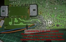
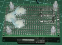
I fitted the RCAs and caps as I thought it would give me something to work around in terms of how to physically place the various additions in the space available, if that makes sense.
I fitted the RCAs and caps as I thought it would give me something to work around in terms of how to physically place the various additions in the space available, if that makes sense.
No but that does not matter anymore as the holes are already there.
You intend to bypass output stages but why? Maybe the idea can be to improve or replace output stages, I am sure it will lead to better results. The output stages are the interface of noisy 1 bit DACs to the analog world and can not be omitted.
The datasheets are one of the few sources for correct information, they should be seen before doing any assumption. In this case one can be assured of instant improvement when upping the PSU to +/- 9V or +/- 12V even with M5218. So... the PSU must be changed anyhow for either any new output stage or the original circuit and is a given. My suggestion is to make a drawing where you can put it.
Last edited:
You misunderstand me, I only want to change things that are worth changing in terms of giving a tangible benefit, I just mentioned I have a variety of different caps I can use because I want to learn what type is best used in what place and why, for instance, there are a few 47uF electrolytics scattered about the player, I have some Nichicon low ESR electrolytics and solid tantalums in that value, but I'm not going to blindly rip out the existing caps and replace them, I'm going to study the circuit and seek advice before changing anything so I learn the underlying technical knowledge and understand why it was a good idea to replace those caps.
The clock module, I assume you are talking about the AMS1117 regulator? I could try to remove it and replace it with a better regulator, I have some HT7333s that are also in the SOT-89 package and would be a direct replacement.
If not, I suppose I'll have to look at building a low jitter clock circuit, I can salvage the crystal from the crappy Chinese one.
Sorry but it is your own information that lead to my view. You already wanted to bypass the output stage and were already busy changing/replacing caps. The holes are also already drilled..
Anyway, I think it can be done more optimal with some thought. This takes a different way of looking at things. To value what is already good and to change less optimal sections to a higher level with elegant craftsmanship. Choose new parts with care and best-for-the-purpose.
The HT7333s has no data on noise in the datasheet and therefor is likely even worse than AMS1117. The latter has no place in any serious design. Have you checked its datasheet? Please do so and tell me why we shouldn't use it.
Last edited:
I always intended to replace the output stage as all the reading I have done points to the output stage as being the area of CD players where the most tangible improvements can be made, not least because the designs used and often pretty crappy, with multiple opamps of old, not very good types. There's plenty of room to fit a new supply for the output stage, my concern is which bit of space in which to place the supply in order to minimise the distance and avoid long cable runs connecting the supply to the output stage. The existing power supply arrangements are not very impressive, it is tempting to completely redo the power supply section altogether, with a new AC socket, transformers etc. The lack of AC filtering is something I'd like to do something about, either by using the Schaffner IEC socket I have with built-in filtering or by fitting the small filter board I have.
That is all assumptions and generalized info from others. Many very well tested and valued devices have opamp output stages. It is surprising to see supposedly inferior opamps performing just fine in a well designed output stage. Still discrete and transformer based designs are preferred by many.
The trick is to look at every device with "fresh eyes" and do specific design per device. As stated, this device needs a new PSU +/- 9 ...12V 100 mA minimum and it needs a better clock with a clean supply voltage and some fresh filter caps. After having done that one can still evaluate and see if replacing the output stage is needed.
The trick is to look at every device with "fresh eyes" and do specific design per device. As stated, this device needs a new PSU +/- 9 ...12V 100 mA minimum and it needs a better clock with a clean supply voltage and some fresh filter caps. After having done that one can still evaluate and see if replacing the output stage is needed.
Last edited:
I've looked at the AMS1117 datasheet and I'm guessing that the 0.003% RMS output noise at 25C between 10hz and 10kHz doesn't tell the whole story about the noise on it's output and most likely as the temperature increases, so does the noise, perhaps in a very logarithmic relationship so that as the temperature increases, the noise increases by a very significant amount? When I originally bought this clock module a few years ago, I must have looked at the AMS1117 datasheet as I replaced the 10uF electrolytic cap on the module with a 22uF tantalum, as prescribed in the datasheet, I wouldn't have known to do that without having read the datasheet.
Discrete output stages are the preference of a great many people, according to what I have learned so far. I understand that there are important improvements to be made to the caps, clock and power arrangements, I always intended to do those things, but I really don't think there's much, if any prospect of retaining the existing output stage, it is surely not difficult to improve on the design used, even if it is just to use better opamps and remove the muting transistors.
Discrete output stages are the preference of a great many people, according to what I have learned so far. I understand that there are important improvements to be made to the caps, clock and power arrangements, I always intended to do those things, but I really don't think there's much, if any prospect of retaining the existing output stage, it is surely not difficult to improve on the design used, even if it is just to use better opamps and remove the muting transistors.
Different view, I would focus on solving issues at the root and take care to check the basis. When such stuff is optimal or optimized then the output stage can be looked at. Now I dare to assume: when the PSU of the opamps is upped you will have improvements in audio quality, maybe even more than just replacing the opamp for a better one while leaving the PSU +/- 5V 🙂
AMS1117 has around 100 µV of noise.
AMS1117 has around 100 µV of noise.
Last edited:
I don't disagree with you, and I think you're right, it is highly likely that improving the PSU arrangements will yield sonic benefits. I just started with the assumption that the analogue stage is being replaced, other than that, I think my approach is pretty much as you suggest.
I couldn't find any noise figure in the datasheet, but I did read that LT1763-3.3 has 20uV noise and ADM7150-3.3 has 1.6uV noise. That means ADM7150-3.3 has about 2% of the noise of AMS1117.
I suppose I could try to replace the AMS1117 on this clock module, but I think it would be better to ditch it and build something else. Do you happen to have any suggestions for low jitter clock circuits?
Hi I used a lot of Tent modules both DIY and the ready made versions.
ADM7150-3.3 seems a good candidate as the XO with its current AMS1117 won't bring improvement. FWIW I obtained a lot of industrial linear PSU's in the right values all new and unused. These are cheap, discretely built (!!) and very low noise, have 240V mains inputs and mains transformer on board. My tests with them are satisfying till now. I just checked and I have them in +/- 12 ...15V with an extra PSU that outputs 5..6V 1A. Maybe that one can be modified to 3.3V. Not wanting to sell you a vacuum cleaner but if you can use one of these send me a PM. As these can be mounted with just 4 screws a lot of practical difficulties are solved at once.
ADM7150-3.3 seems a good candidate as the XO with its current AMS1117 won't bring improvement. FWIW I obtained a lot of industrial linear PSU's in the right values all new and unused. These are cheap, discretely built (!!) and very low noise, have 240V mains inputs and mains transformer on board. My tests with them are satisfying till now. I just checked and I have them in +/- 12 ...15V with an extra PSU that outputs 5..6V 1A. Maybe that one can be modified to 3.3V. Not wanting to sell you a vacuum cleaner but if you can use one of these send me a PM. As these can be mounted with just 4 screws a lot of practical difficulties are solved at once.
Last edited:
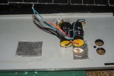
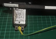
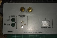
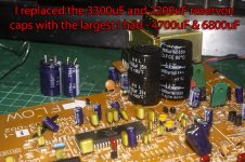
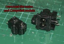
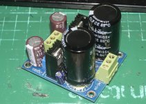
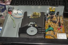
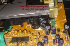
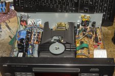
I dismantled the player so I can rework the power supply arrangements. I've fitted a 3-pin Schaffner socket that has a built-in AC filter for cleaner power. I've replaced the reservoir caps with the largest ones I had - 4700uF and 6800uF replacing 2200uF and 3300uF. I'm going to add a second trafo with dual 18v secondaries and an LM317/337 board to power the analogue output stage. I'm also going to add some 5v regulators too, not sure if I'll add another trafo for those, I might have one with 6v secondaries, I'll have to check. I plated over the holes left in the back after removed the mains socket and the Compulink socket.
Attachments
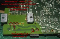
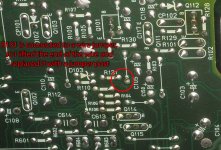
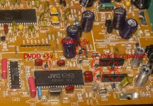
I discovered that I don't need to lift one end of R313 as R313 is connected to a wire jumper so I lifted one end of that wire jumper and fitted a jumper pin so I can connect a +5V supply.
I'm wondering now what other caps I should replace.
I'm wondering now what other caps I should replace.
Attachments
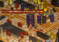
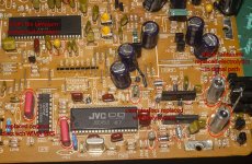
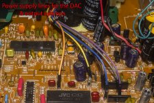
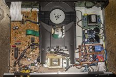
I recapped the whole board, all the electrolytics have been replaced, the small values under 100uF with tantalums, the larger ones with electrolytics, mostly low ESR Rubycon 1500uF. The ceramic disk caps have all been replaced too with the smaller values replaced by polystyrene and the larger ones by Wima MKS4. The two 100uF electrolytics in the output stage which are in the signal path have been replaced by 100uF tantalums.
I've identified the correct points where clean power supplies to the DAC and opamps should be connected, in all cases there were wire jumpers that could be removed and replaced with jumper pins. So there are now jumpers to connect power to both the digital and analogue sides of the DAC and to both opamps, I don't think i can improve thee power delivery any more than that.
To power the opamps, I have an LM317/337 board, I've replaced the large caps on it as I was suspicious of the ones fitted, probably Chinese fakes. 3300uF 'Nickicons' have been replaced by 6800uF Dubiliers and 100uF by Nippon Chemi Com. 470uF.
So now I have to put it all back together and build and install two +5v supplies and a +/- 9v supply for the opamps - I'm only using 9v as the 100uF tantalums I fitted are only rated for 10v, which might be a compromise I shouldn't make, but as I stated early in the thread, this is a learning exercise so I'll see how 9v works.
Not done anything about fitting a new clock, I can always return to that issue later if everything else works.
Attachments
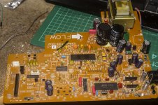
Well, so far, so good. I've reassembled the player and it works fine in that it powers up, reads a disk and plays it. There is no sound obviously, as there is no power to the DAC or output opamps, but at least I've verified all the work done so far is okay.
Now to build and install a dual rail supply for the opamps and a pair of +5v supplies for the DAC....
Now to build and install a dual rail supply for the opamps and a pair of +5v supplies for the DAC....
Attachments
Last edited:
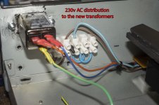
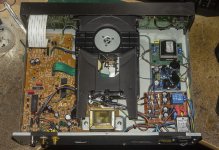
I found a PCB mount transformer with a pair of 9v secondaries in my stash of parts so I used that to create a dual rail supply in conjunction with the LM317/337 board. I decided to use the mini PSU I showed earlier in the thread for the +5V supplies, only one half is needed, so there are two spare +5V supplies that could be used for further mods.
I assembled it all and it works in that it powers up and there are no sparks or magic blue smoke, but I must have damaged something in either the drive mechanism or the servo electronics as it doesn't spin the disc. Oh balls, I shall have to try to diagnose the issue. Hope it's something simple.
I'm quite happy with how it's turned out, so I really want to fix the drive issue and hear what it sounds like now.
Attachments

Not diagnosed the problem yet, it still won't spin the disc. Only thing I changed in the drive section of the board was to replace two or three small electrolytics.
Anyone got any tips/advice on how to diagnose the issue?
Anyone got any tips/advice on how to diagnose the issue?
- Home
- Source & Line
- Digital Line Level
- CD player upgrade project