Well, the Arcam DV88 finally reached me and it's dead as a dodo, no signs of life at all.
It might be the switch as it seems a bit funky.
I'll start a new thread about trying to repair it.
Meanwhile, I'll find another player to use for this upgrade project.
It might be the switch as it seems a bit funky.
I'll start a new thread about trying to repair it.
Meanwhile, I'll find another player to use for this upgrade project.
Thats a shame Ian. But maybe its just a blown internal fuse....maybe also wishful thinking!
I'm just sat listening to a Pioneer DV-2750...won on ebay for a fiver. Sounds very good to my ears. I've just done a couple cap changes and additions. Been reading the service manual for a while to get my head around it....seems there are quite a lot of 'no fit' components and so there is an easy enough route to improvement. Trouble being the pcb is awful to solder. Already damaged one through hole on a simple cap swap. So I don't think I'll go mad with it.
I had one of these new back in the early 00's. I remember taking it to a high end independent retailer to demo some of their AV wares. The proprietor was embarrassed at how good it was back then.
It was killed in a lightning strike to our home. I binned it. Knowing what I know now it was probably just the pcb fuse on the smsp that blew!
Occasionally, I have seen power transformers with an open winding. There is sometimes an internal safety fuse that is not replaceable.
There's a couple of internal fuses in the Arcam, neither has blown. The service manual states the next step is to check the power rails but doesn't specify where these rails are or how to check them.
🙄You sound pretty good at reading schematics so I'm sure you can suss it out.!
In other news and despite my last comments on my cheap dvd player; I spent a couple hours yesterday fitting an LT3042 as the 3v3 rail to the dac. Seems the 3v3 doesn't have a local regulator and is derived straight from the smps and so is shared by all the digital ICs. It took a trace cut but other than that wasn't too bad a job.
Amazingly it seemed to sound worse🙄 will listen again tonight.
Been trying to fathom if I can replace the 27Mhz crystal with a Flea I have here with a decent enough crystal on there. The player will only be for CDs.
You have more faith in my ability than I do Jim!
I got a refund on the Arcam, it's going to sit in the pile of things to be fixed for the time being. I'll study the service manual and see what I can decipher.
I'm still on the hunt for a suitable player to use for this upgrade project, there are so many choices, I missed out on a Harman Kardon HD720 to some sniping git, wanted that because it is fully discrete, not an opamp or IC anywhere besides the essential chips needed for a CD player.
Regarding the Arcam, you might try connecting an ohmmeter the line cord prongs (with the unit unpowered, of course), and measure the resistance with the power switch turned on. Is it megaohms?
Hope you fathom something out.
I removed the LT4032 from the digital 3v3 rail on the DV 2750 and it is back sounding good again. Strange.
On the DV717, well I hadnt realised quite how deep I will need to go to feed it with i2s. There are lots of muting transistors on the voltage regs and I'm not sure how much time I want to spend on it. I havent even heard the PCM1716 or indeed in this implementation and so don't know if I'll like it after all the effort! Would be quicker to rip it out and just use the chassis for the CD rom and miro ad1862. We'll see!
The PCM1716 is very well regarded in some circles despite being one of the cheaper chips in Burr-Brown's range at that time, I imagine two of them will sound pretty good if the peripheral electronics are sorted.
The thing that puts me off playing with something like that Pioneer is the complexity, so I'm interested to know how you get on.
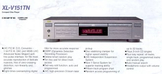
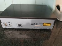
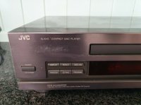
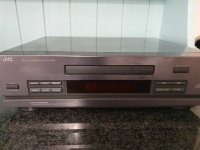
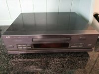
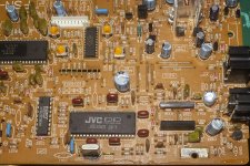
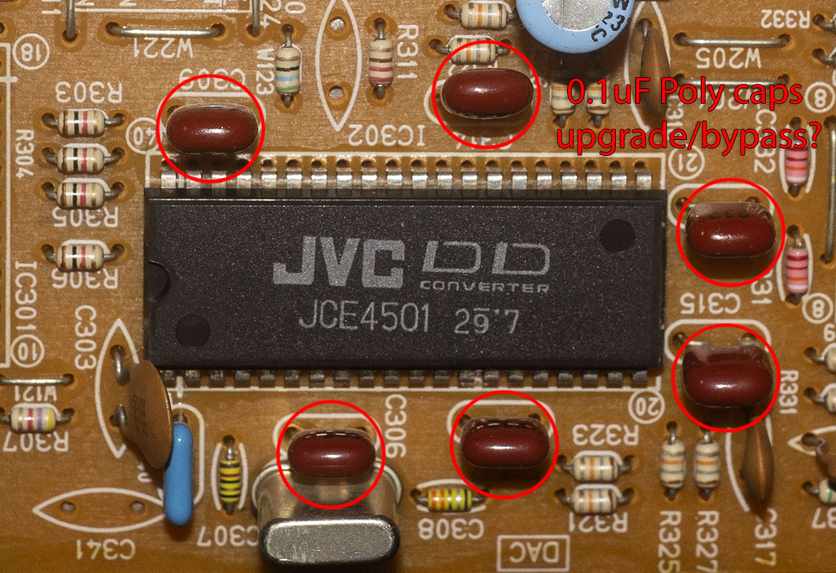
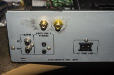
I've finally obtained a CD player to work with, got it locally dirt cheap, it's a JVC XL-E45, a midi sized thing close to the bottom of their range, but it has the desirable 1-bit P.E.M. D.D. converter at it's heart, sadly it doesn't also have the very desirable K2 processing chip.
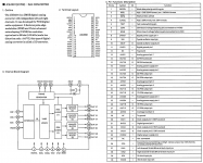
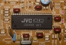
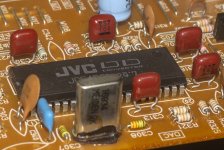
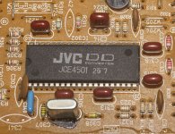
The "1-bit P.E.M. D.D. converter" is the marketing speak, but it denotes the JCE4501 DAC, created by JVC themselves and it is an unusual one as it uses Pulse Edge Modulation (PEM) rather than the usual PCM and has a total of 8 outputs.
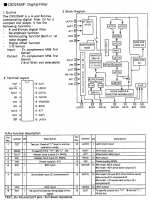
Here's some details from the service manual and some JVC literature:
P.E.M. D.D. Converter with VANS, fine pulse interface
The DD (Digital Direct) converter is carried in the D / A conversion part.
In the DD converter, the digital signal is converted into a 1-bit operation pulse wave that changes based on the crystal clock, and is directly converted to analog. Therefore, unlike the conventional ladder type D / A converter, since the bit amount is not piled up, zero cross distortion due to the amplitude error does not occur in principle, and the reproduction ability of a minute level is greatly improved. Furthermore, the excellent characteristics of a dynamic range of 100 dB or more and a distortion rate of 0.0017% or less are realized.
The DD converter consists of three parts: digital filter + noise shaper + PEM / DAC, all of which are digitally processed.
In the early '90s JVC developed a proprietary circuit for a more accurate D/A conversion, called P.E.M. (Pulse Edge Modulation, in contrast with the common PWM, Pulse Width Modulation) which gave a big "plus" to their CD players so that even the most die-hard audiophiles had to recognize those machines played extremely good noises.
In particular, that circuit allowed the JVC CD players to reach the limit of the maximum theoretical CD digital resolution, approaching 15.9 dB (theoretical max being 16 dB).
1-bit digital-to-analog (D/A) converters use a form of pulse-width modulation (PWM) that JVC calls PEM DD (for Pulse Edge Modulation Differential-linearity-error-less D/A conversion). They employ variable noise shaping, up to the fourth order, to minimize quantization noise (other 1-bit systems currently use fixed second- or third-order noise shaping). Two PEM converters per channel are used for maximum low-level linearity with minimum distortion and noise.
The thing that puts me off playing with something like that Pioneer is the complexity, so I'm interested to know how you get on.
I've finally obtained a CD player to work with, got it locally dirt cheap, it's a JVC XL-E45, a midi sized thing close to the bottom of their range, but it has the desirable 1-bit P.E.M. D.D. converter at it's heart, sadly it doesn't also have the very desirable K2 processing chip.
The "1-bit P.E.M. D.D. converter" is the marketing speak, but it denotes the JCE4501 DAC, created by JVC themselves and it is an unusual one as it uses Pulse Edge Modulation (PEM) rather than the usual PCM and has a total of 8 outputs.
Here's some details from the service manual and some JVC literature:
P.E.M. D.D. Converter with VANS, fine pulse interface
The DD (Digital Direct) converter is carried in the D / A conversion part.
In the DD converter, the digital signal is converted into a 1-bit operation pulse wave that changes based on the crystal clock, and is directly converted to analog. Therefore, unlike the conventional ladder type D / A converter, since the bit amount is not piled up, zero cross distortion due to the amplitude error does not occur in principle, and the reproduction ability of a minute level is greatly improved. Furthermore, the excellent characteristics of a dynamic range of 100 dB or more and a distortion rate of 0.0017% or less are realized.
The DD converter consists of three parts: digital filter + noise shaper + PEM / DAC, all of which are digitally processed.
In the early '90s JVC developed a proprietary circuit for a more accurate D/A conversion, called P.E.M. (Pulse Edge Modulation, in contrast with the common PWM, Pulse Width Modulation) which gave a big "plus" to their CD players so that even the most die-hard audiophiles had to recognize those machines played extremely good noises.
In particular, that circuit allowed the JVC CD players to reach the limit of the maximum theoretical CD digital resolution, approaching 15.9 dB (theoretical max being 16 dB).
1-bit digital-to-analog (D/A) converters use a form of pulse-width modulation (PWM) that JVC calls PEM DD (for Pulse Edge Modulation Differential-linearity-error-less D/A conversion). They employ variable noise shaping, up to the fourth order, to minimize quantization noise (other 1-bit systems currently use fixed second- or third-order noise shaping). Two PEM converters per channel are used for maximum low-level linearity with minimum distortion and noise.
Attachments


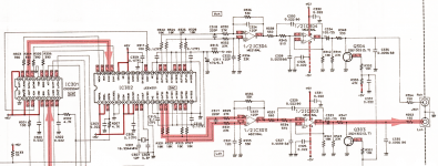
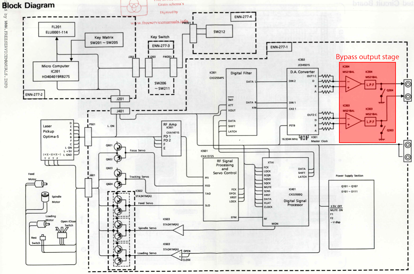
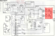
Here's the schematics of the DAC and analogue output stages. The decoder ship is a Sony CXD2554P which means I can't do a NOS mod as the Sony chip separates the data input into right and left before passing it to the DAC.
The obvious mod to do here is to bypass the output stage and replace it with one of my own construction. The other things to do are replace the caps with better ones and give the DAC it's own clean, regulated power supply.
The obvious mod to do here is to bypass the output stage and replace it with one of my own construction. The other things to do are replace the caps with better ones and give the DAC it's own clean, regulated power supply.
Attachments

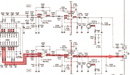

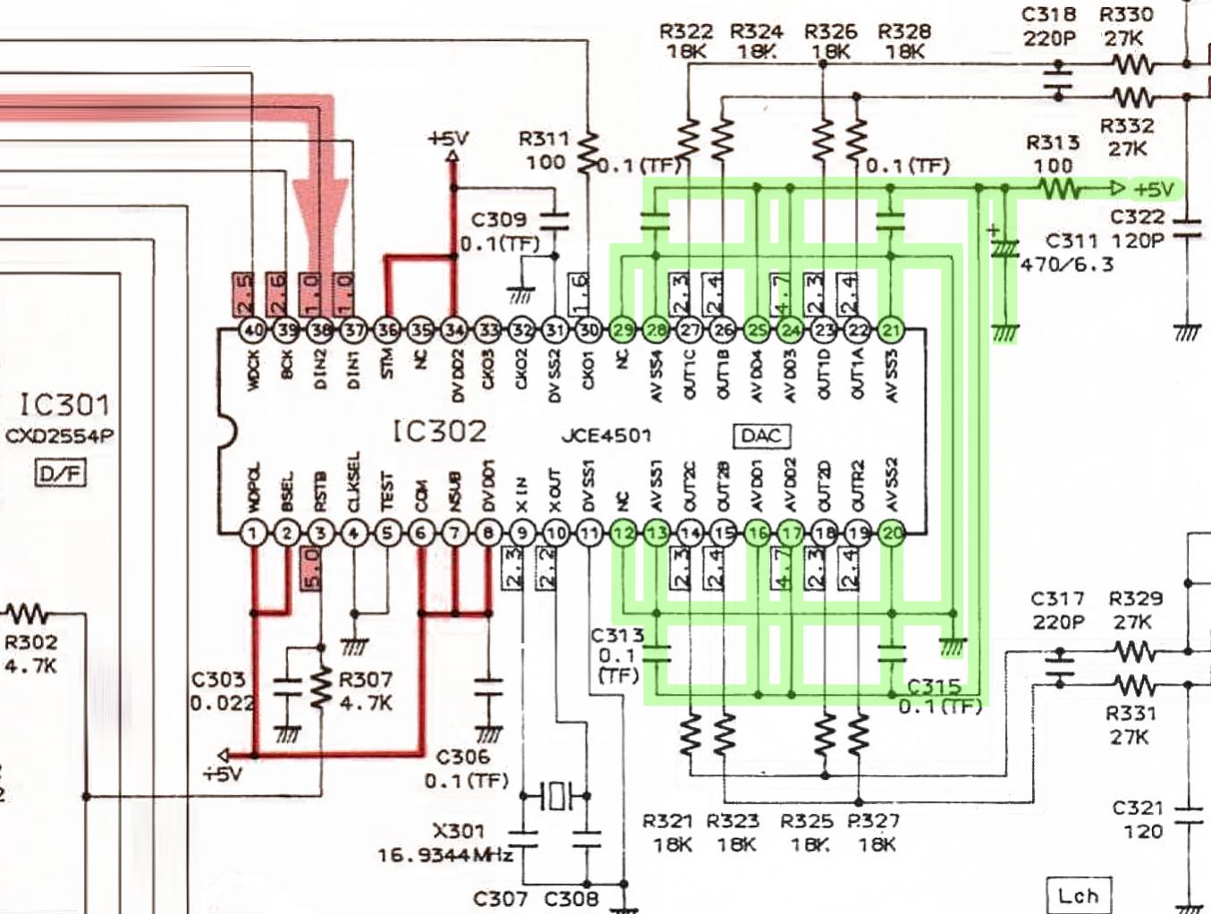
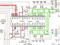
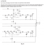
Obviously, the output stage needs to go:
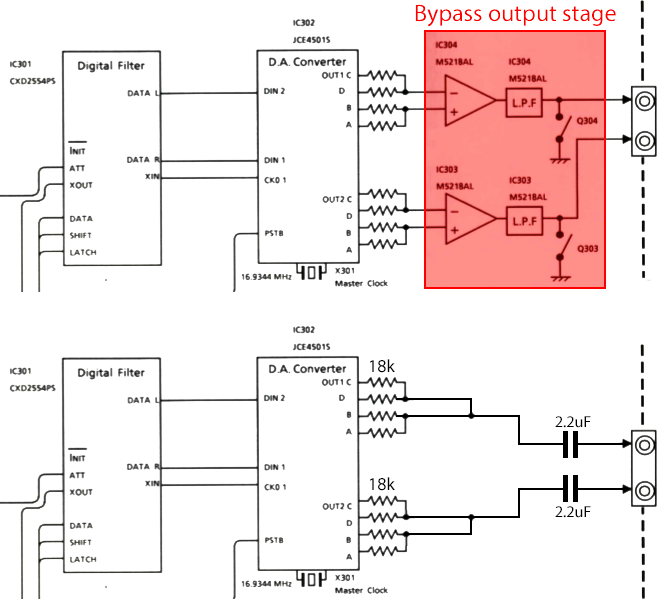
It uses a pair of dual opamps, one half of each is a summing amplifier, the other half an active LPF. I think the18k resistors are performing the I-V conversion. I suppose I could try just connecting the outputs directly to a pair of DC blocking caps, but I will probably need to add a LPF of some kind.
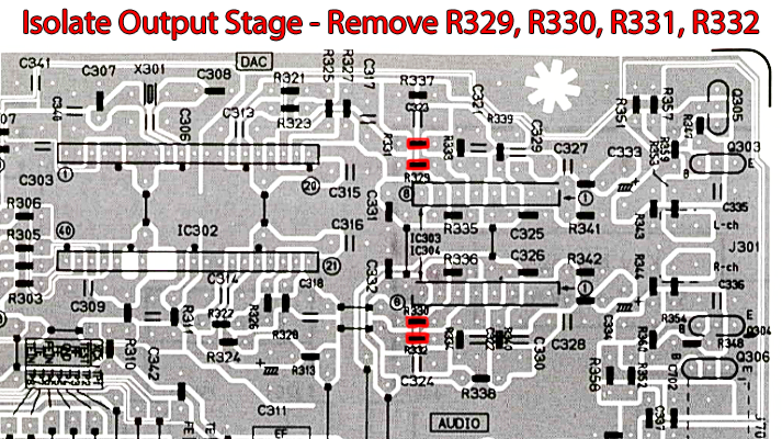
It's not hard to isolate the output stage, there are four conveniently placed resistors that could be removed.
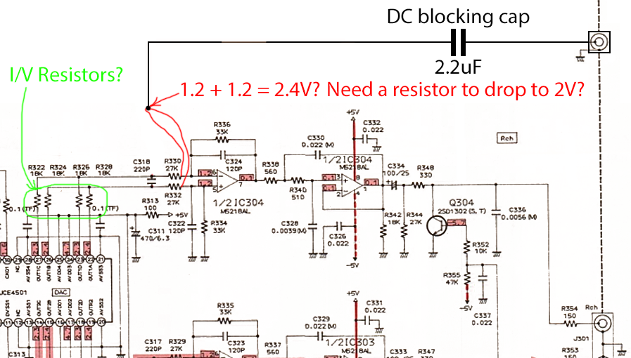
Am I interpreting the schematic correctly? The 1.2 in the little red box is the voltage at the input of the opamp, if I join those two inputs together, do I get 2.4v? Is this too high and I need to drop it to the 2.0v RMS that is usual for line level? I'm guessing 2.4v will be okay, it will just sound louder so I'll need to turn the amp it's hooked up to down a little?
It uses a pair of dual opamps, one half of each is a summing amplifier, the other half an active LPF. I think the18k resistors are performing the I-V conversion. I suppose I could try just connecting the outputs directly to a pair of DC blocking caps, but I will probably need to add a LPF of some kind.
It's not hard to isolate the output stage, there are four conveniently placed resistors that could be removed.
Am I interpreting the schematic correctly? The 1.2 in the little red box is the voltage at the input of the opamp, if I join those two inputs together, do I get 2.4v? Is this too high and I need to drop it to the 2.0v RMS that is usual for line level? I'm guessing 2.4v will be okay, it will just sound louder so I'll need to turn the amp it's hooked up to down a little?
Attachments


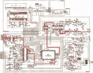
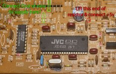
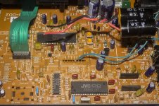
The 6 caps circled are 0.1uF and connected between the +5v supply and ground, they look like polyester caps to me, so I can replace them with polypropylene. I have 0.1uf EVOX polypropylene caps in my stash, I also have larger polyprops, is there any benefit to increasing the value from 0.1uF?
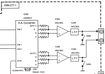
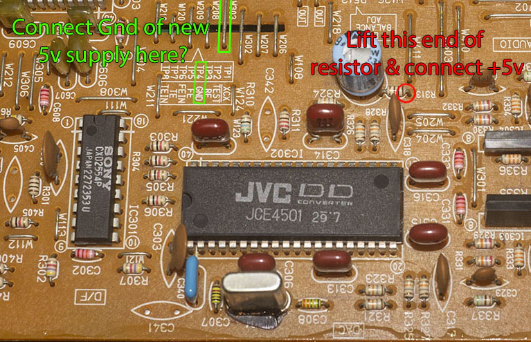
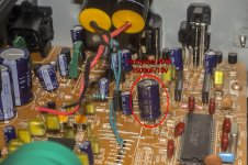
Here's the power supply arrangements for the DAC, it looks like it is a simple task to lift one end of resistor R313 and connect a new clean 5v supply for the analogue side of the DAC chip.
R313 is easy to access, the electrolytic cap next to it is a bog standard type 470uF, I'll replace it with a 1500uF/10v Rubycon MBZ low ESR which are highly rated for use on computer motherboards, in fact I read that they were the best caps made for that use, so they should be ideal for use here. There's a wire jumper close by labelled 'TP4 GND' which I think is a good place to connect the GND of the new power supply?
Attachments

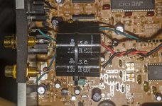
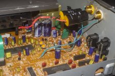
I've made a start by fitting a new set of RCAs and connecting a pair of DC blocking caps to them. I used a pair of T.S.E. 2.2uF polypropylene caps, which are a step up in quality from the Chinese brands. I connected the grounds from the RCAs to the wire jumper labelled 'TP4 GND'. I also replaced the 470uF/6.3v 85C grounding cap with a low ESR Rubycon MXB 1500uF/10v 105C.
Attachments
Your device had an output/summing filter stage for a reason. Just a cap won't do. I have modded such devices with discrete non-feedback circuits with very good results.
I pity the device following as there is no GND reference resistor and no muting. Simplicity is good but too simple is not good.
I pity the device following as there is no GND reference resistor and no muting. Simplicity is good but too simple is not good.
Last edited:
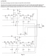
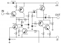
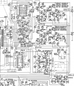
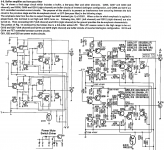
Yes, I realised there would need to be more than just a cap. I've been studying various discrete output stages, here's a couple of Harman Kardon designs I could perhaps adapt.
Do you have any suggestions for what would be most suitable for this JVC JCE4501 DAC, it's quite unusual I think with the four pairs of balanced outputs.
I suppose I will need I-V conversion, LPF and a buffer of some kind.
For muting, I suppose that relays are superior to transistors, although I have no idea how to implement a relay and almost every service manual schematic I have studied, which is more than a few, uses transistors, I suppose because it is a cheaper solution than relays.
Attachments
-
 HK Low Pass Filter.png81.2 KB · Views: 118
 -
 HD720-Audio Circuit 2.png109.5 KB · Views: 106
 -
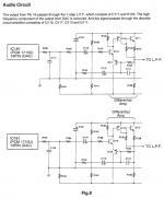 HD720-Audio Circuit 1.png85.2 KB · Views: 126
 -
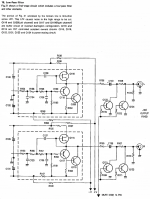 discrete Low Pass Filter.png158.2 KB · Views: 139
 -
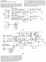 Vout DAC discrete output stage 2.png193.3 KB · Views: 110
 -
 Vout DAC discrete output stage.png57.5 KB · Views: 125
 -
 Harman-Kardon HD7400 discrete output stage 2.png557.6 KB · Views: 177
 -
 Harman-Kardon HD7400 discrete output stage.png439.3 KB · Views: 236
Last edited:
The four outputs make no difference as these are tied together. The original M5218 circuit is not the best as the opamp is not that good. So logic tells to replace that circuit with a similar functioning circuit that filters and it suitable for balanced inputs. Least effort would be to replace M5218 for a modern opamp like OPA1642 or OPA1656 on a self designed adapter PCB. Most effort is to create a new board with a superior circuit. Both suggestions are based on the premise to do stuff right.
Please consider finding out stuff first before doing any action. Your assumption that the caps are 0.1 µF polyester is wrong. These are the very good TF (Teflon Film) caps which should stay where they are! Your assumption on the relays is right, these are way better but they are too expensive and unfortunately too slow for some purposes. For power on muting I would never use transistors.
The device probably needs a recap more than anything else first. From experience I can tell that removing the crystal and placing a low jitter clock in these players has much impact.
Last edited:
I don't intend to modify the existing output stage, but rather, create a replacement, which is, as you point out, the right way of doing it.
I am indeed trying to learn before doing things, that was the whole point of asking about those caps before doing anything to them, thankyou for that piece of info, I had wondering what the TF stood for in the schematic.
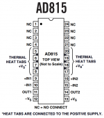
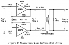
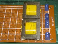
I happen to have just obtained and soldered to adapters some AD815 opamps, perhaps I can use those. I also have some 1:1 transformers and the AD815 in it's original role is intended to drive a transformer, so it strikes me that an AD815-transformer solution might work well?
I am indeed trying to learn before doing things, that was the whole point of asking about those caps before doing anything to them, thankyou for that piece of info, I had wondering what the TF stood for in the schematic.
I happen to have just obtained and soldered to adapters some AD815 opamps, perhaps I can use those. I also have some 1:1 transformers and the AD815 in it's original role is intended to drive a transformer, so it strikes me that an AD815-transformer solution might work well?
Attachments

- Home
- Source & Line
- Digital Line Level
- CD player upgrade project